MICROMECHANICAL MODELLING OF TEST SPECIMENS FOR ONSET OF - - PDF document

micromechanical modelling of test specimens for onset of
SMART_READER_LITE
LIVE PREVIEW

MICROMECHANICAL MODELLING OF TEST SPECIMENS FOR ONSET OF - - PDF document

18 TH INTERNATIONAL CONFERENCE ON COMPOSITE MATERIALS MICROMECHANICAL MODELLING OF TEST SPECIMENS FOR ONSET OF DILATATIONAL DAMAGE OF POLYMER MATRIX IN COMPOSITE MATERIALS T. D. Tran 1 , D. Kelly 1* , G. Prusty 1 , G. Pearce 1 1 School of


slide-1
SLIDE 1

18TH INTERNATIONAL CONFERENCE ON COMPOSITE MATERIALS

1 Introduction Recently, Gosse and Christensen [1] and Hart- Smith [2] have proposed a micromechanics failure theory for composites, called Strain Invariant Failure Theory (SIFT), or more recently the Onset Theory [3]. The onset theory is considered to be rigorous and have unique advantages over traditional failure theories in that it is suitable for all possible laminate lay-ups, geometric configurations, loading and boundary conditions. To implement the theory, macroscopic strains determined by structural finite element analyses are enhanced by micromechanical strain amplification factors to determine representative strains at the microscopic level. Damage onset is predicted by comparing the micromechanical strain state to a set of critical strain invariants. In this paper, only matrix damage onset is

  • considered. Damage onset within the fiber phase

is addressed elsewhere [4]. Gosse et al [1,3] have proposed that the polymer matrix fails either by yielding or by cavitation. Matrix cavitation is related to dilatational volume increase while yielding is related to dilatation free distortion. Therefore, failure initiation in the matrix phase is predicted by comparing the first dilatational strain invariant or a modification of the second distortional strain invariant to critical values determined from coupon tests. An important step in the theory is the establishment of the critical values of the strain invariants as material properties for the matrix. Work reported in [3] proposed

  • ff-axis

unidirectional tests to generate these critical

  • values. A 100 specimen gives the critical invariant

for distortional behavior, while a 900 specimen gives the critical invariant for dilatational

  • deformation. Finite element models of the test

specimens are used to model the specimen at failure and back out the critical values as values using strains enhanced by the magnification factors. Modeling the response of the off-axis tensile tests is however challenging due to stress concentrations, especially for the cases where the fiber angle is 100 [3]. Furthermore, using the continuum models to obtain the critical values requires strain enhancement factors to determine strains in the resin and fibers which takes time and

  • effort. To overcome these issues a new

micromechanics modeling approach has been

  • proposed. Application to modeling of the 100 off-

axis specimen will be published elsewhere [5]. In this paper, the focus will be the 900 specimen including testing and micromechanical modeling. 2 The Damage Onset Theory In the approach proposed by Pipes and Gosse [3] strains from a continuum model of the laminate are enhanced by micro-mechanical strain amplification factors to determine strains in the resin including thermal residual strains from the

  • cure. These amplification factors are determined

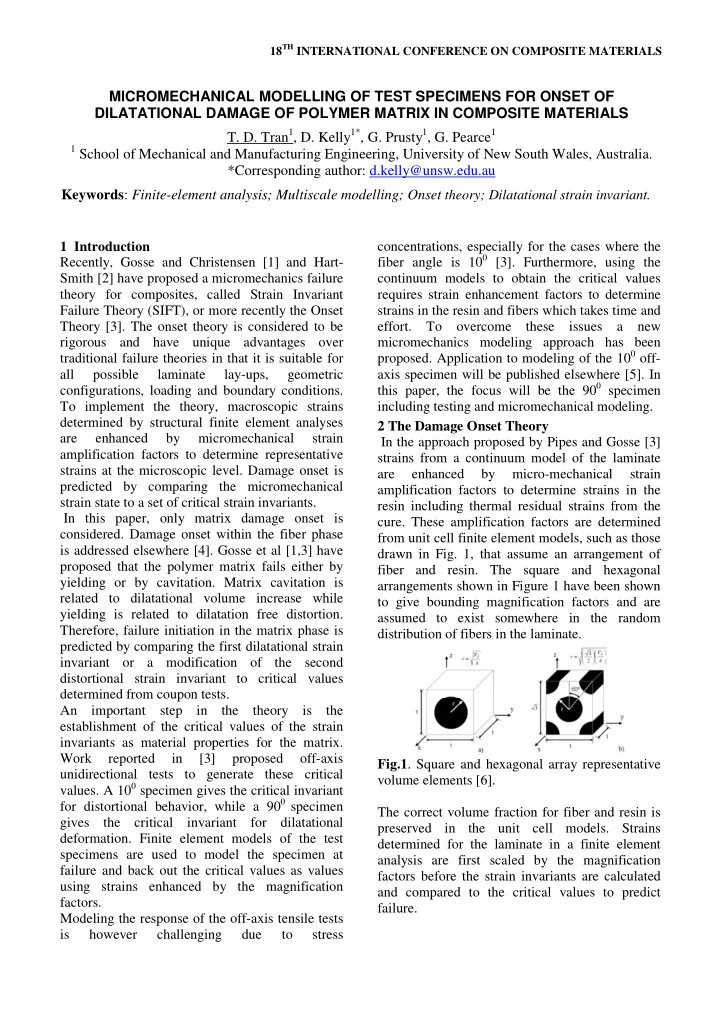
from unit cell finite element models, such as those drawn in Fig. 1, that assume an arrangement of fiber and resin. The square and hexagonal arrangements shown in Figure 1 have been shown to give bounding magnification factors and are assumed to exist somewhere in the random distribution of fibers in the laminate. Fig.1. Square and hexagonal array representative volume elements [6]. The correct volume fraction for fiber and resin is preserved in the unit cell models. Strains determined for the laminate in a finite element analysis are first scaled by the magnification factors before the strain invariants are calculated and compared to the critical values to predict failure. MICROMECHANICAL MODELLING OF TEST SPECIMENS FOR ONSET OF DILATATIONAL DAMAGE OF POLYMER MATRIX IN COMPOSITE MATERIALS

  • T. D. Tran1, D. Kelly1*, G. Prusty1, G. Pearce1

1 School of Mechanical and Manufacturing Engineering, University of New South Wales, Australia.

*Corresponding author: d.kelly@unsw.edu.au Keywords: Finite-element analysis; Multiscale modelling; Onset theory; Dilatational strain invariant.

slide-2
SLIDE 2

Mathematically, the relationship between the micro-strains and the macro-strains of a uni- directional composite laminate is given as [3,6]:

∆ = ̅ −

∆ +

∆ (1)

(, = 1 − 6) where: ̅

∆ = macro-strains due to mechanical and thermal loads

∆ =micro-strains at the kth point in the

representative volume element (RVE)

  • =strain enhancement matrix at the kth point in

the Representative Volume Element (RVE) in Fig. 1

  • =thermal strain vector due to CTE mismatch of

fiber and resin ∆=temperature drop from curing temperature to

  • perating temperature
  • = effective coefficient of thermal expansion of

the laminate

  • = coefficient of thermal expansion of fiber or

matrix depending on the kth point in the RVE. The onset theory states that if either the dilatational strain invariant or the distortional strain invariant exceeds their respective critical values, damage initiation occurs [3, 6]. The reduced form of the dilatational strain invariant is as follows:

3 2 1

ε ε ε ε + + =

dil

(2) and the distortional strain invariant is defined by:

( ) ( ) ( )

[ ]

2 3 2 2 3 1 2 2 1

6 1 ε ε ε ε ε ε ε − + − + − =

dis

(3) where:

dil

ε

=dilatational strain invariant

dis

ε

=distortional strain invariant

i

ε = principal strains.

The detailed procedure for the micromechanical enhancement, including boundary conditions applied to the RVE, is discussed in [6]. With the aid of micromechanical enhancement, a detailed assessment of irreversible deformation is possible beyond the homogenous deformation state [3,6]: Damage onset within the matrix phase is identified as: If

critical dil dil

ε ε ≥ , the matrix will cavitate. If

critical dis dis

ε ε ≥ , the resin will yield. Here

critical dil

ε = the critical value for dilatation deformation

critical dis

ε = critical value distortional deformation. Damage onset within the fiber phase is not addressed in this paper. Equation (1) emphasizes that intralaminar residual thermal effects are taken into account at the micromechanical level as well as at the laminate (or interlaminar) level. As long as

critical dil

ε and

critical dis

ε for the polymeric matrix are known, the assessment of damage onset for the polymeric matrix of composite structures can be performed. Damage and crack propagation are actually a repeated damage initiation phenomenon and therefore a credible simulation of these damage crack phenomena must be driven by the critical material properties of the constituent materials. All effective interfacial phenomena are assumed to be subsumed within the bulk response from the test. 3 Experiment for critical strain invariants for the matrix To determine the critical values of the strain invariants for the matrix, it would make sense to conduct experiments directly on the polymer matrix

  • f

the composite. However, the deformation of the polymer matrix in real unidirectional laminates is constrained by the

  • fibers. To achieve this constrained strain state in a

neat resin test is a non-trivial problem which is still under investigation. Currently the most practical way of determining the critical invariants for the matrix phase is via unidirectional composite tensile tests and then finite element analysis of these tests. The latest approach reported in [3] proposed a set of different off-axis unidirectional tests from 100 to 900 to generate critical values of strain invariants for the matrix. A 00 specimen will fail in the fibers and therefore is not included in this set for matrix failures. The reason for choosing this set of tests is that the

  • nset and ultimate failure typically occur

simultaneously in the off-axis tensile test in contrast to the general case for ultimate behaviour wherein damage propagation must occur before

  • nset can be detected. Consequently, the off-axis

tensile test provides an excellent platform for evaluation of the damage onset for the polymer matrix.

slide-3
SLIDE 3

3

Table 1. Properties of lamina CYCOM 970/T300 with fiber volume fraction = 60% . Properties Lamina [7] T300 Fiber [8] CYCOM 970 Epoxy resin [9] E1 (GPa) 135 230 3.3 E2 (GPa) 8 13.8 3.3 E3 (GPa) 8 13.8 3.3 G12 (GPa) 5 8.97 1.22 G23 (GPa) 2.76 4.83 1.22 G13 (GPa) 5 8.97 1.22 ν12 0.25 0.2 0.35 ν23 0.34 0.25 0.35 ν13 0.25 0.2 0.35 α11(/0C) 0.014e-6

  • 0.54e-6

58e-6 α22= α33 (/0C) 32e-6 10e-6 58e-6 Table 2. Failure stress and strain for CYCOM 970/T300 tape 900 off-axis specimen. [90]24 Mean failure stress (MPa) 76 Max axial strain at failure 0.0135 Mean axial strain at failure 0.0128 Coefficient of variation (CV)

  • f axial strain at failure

0.061 By analysing these tests and normalizing both distortional and dilatational strain invariants, Pipes and Gosse [3] found that the 100 specimen gives the critical invariant for distortional behaviour, while the 900 specimen gives the critical invariant for dilatational deformation. In the current paper, 900 off-axis coupons for the critical dilatational strain invariant were fabricated using commercial prepreg CYCOM 970/T300. The properties of this composite material are given in Table 1. Specimens with 24 plies at 900 were fabricated and tested. The CYCOM 970/T300 unidirectional tape was hand layed, bagged, and autoclave cured using industry standard practices in the Cooperative Research Centre for Advanced Composite Structures (CRC-ACS) Laboratory in Bankstown, Sydney, Australia. After the unidirectional panels were cured, thin [00/900]2s strips made of Cytec BMS 8-139 fiber glass were glued on the cured panels to create tabs. The length of the tab is 50mm. Finally, specimens were cut from the panels using a high precision, water-cooled diamond saw. The dimensions of the prepared final specimens were 300 mm long, 10.33 mm wide and 4.89 mm thick. Five 900 specimens were tested in tension using an Instron-3369 machine with a 50kN load cell in

  • place. A clip-on extensometer was attached to the

middle of the test section of the specimens to measure the axial failure strain. The gauge length for the extensometer was 50mm. All testing data were automatically recorded by the Bluehill software available with the Instron machine. The tests were carried out in displacement control with the loading rate of 2 mm per minute. The mean as well as the coefficient of variation of the strains at failure for the 900 specimens are presented in Table 2. As the analysis is to define a material property, any defect may reduce the failure load hence the maximum recorded strain at failure in Table 2 was used for the following analyses. 4 Finite element analysis In order to extract the critical matrix strain invariants, it is necessary to analyse the tests described in the preceding sections to determine the strain invariants at the failure strains. Normally the finite element method is used to model the laminate with layered structural shell or solid 3D continuum elements. The strains are then enhanced by the magnification factors defined using Equation 1. However, modelling the response of the tensile tests is difficult due to stress concentrations in the corners of the grips [3], especially in the case of small angle off-axis

  • tests. These lead to inaccuracies of stress and

strain state in the model which make it difficult to reflect the physical behaviour of the actual test. A new micromechanics-based modelling approach in which fiber and resin is modelled has been presented by the authors in [5]. In this paper, their approach is extended to the 900 specimen. Finite element analysis is used to model the coupon test at the micro level including fiber and matrix. The results are compared with those in the previous approach [3] which used continuum model and micromechanical enhancement factors. It is essential to note that all the finite element analyses performed herein are linearly elastic. This assumption is reasonable since the damage

  • nset theory is based on strain in the polymeric
  • matrix. When constrained by the fibers in

unidirectional laminates, the matrix has been

  • bserved to deform elastically in strain space but

anelastically in stress space.

slide-4
SLIDE 4

The aim of this paper is to extract the critical dilatational strain invariant. For the dilatational deformation, apart from mechanical load, the thermal residual effect of the curing process caused by the difference between the thermal properties of the fiber and matrix must be taken into account. 4.1 Continuum model For the finite element analysis, only the test section of the specimen is modelled. A complete model including the gripping system which simulates load transfer between the frictional grips and the test specimen can also be implemented. However, since the critical dilatational invariant is extracted from the middle of the test section, both models would lead to the same result, hence the test section is modeled for simplicity. The plan view of the geometry for the FEA simulation is a rectangular parallelepiped whose length L is 195 mm, width 10.33 mm and the thickness is 4.89 mm in the z direction. The boundary conditions, loading and analysis procedure for both the continuum model and the micromechanical model are presented in subsection 4.3. In this paper, the continuum model is performed to obtain the value of the dilatational strain invariant to compare with that obtained using the new micromechanical model with the use of material properties in Table 1. 4.2 Micromechanical model The micromechanical model proposed in this paper extends the work by Buchanan et al [6] where a representative volume element of fibers and resin in a square and a hexagonal array is modeled to obtain the strain influence matrices (strain amplification factors) for micromechanical

  • enhancement. In the proposed approach [3], the

fiber square array embedded in resin is modeled for the whole specimen test section (see Figure 2). The square array is used because analyses [3, 6] have shown that this array is more critical.

  • Fig. 2. Micromechanical representative model of

the 900 unidirectional specimens. Fibres are shown in green. The geometrical dimensions of the specimens are same as those of the above approaches with the length 195 mm, width 10.33 mm and thickness 4.89 mm. The elastic properties of fiber and matrix are also presented in Table 1. The volume ratio of fiber is maintained at 60% for all micromechanical models. A local coordinate system whose x-axis is parallel with fiber direction is defined to characterize fiber properties. The purposes of the micromechanical models are to reflect the failure patterns which are supported by experiments and to obtain the critical strain invariants directly without the need of combining strain amplification factors with the continuum

  • model. As a result, validation of the continuum

approach with micromechanical enhancement factors is achieved if there is agreement between the two approaches. 4.3 Boundary conditions, loading and analysis procedures To take the thermal residual effect of the cooling process from curing to room temperature into account, the analysis procedures for the continuum model and micromechanical model are divided into three sub-steps as follows: Step 1: Determine the thermal shrinkage strain in the specimens caused by curing process: Apply ∆T=Troom-Tcuring (stress-free) = -1250C to the unit cell model or to the full micromechanical model (no mechanical load is applied in this step). The boundary conditions are imposed to allow for free translation normal to the surfaces: x=1, y=1 and z=1 for the square array unit cell in Fig. 1a or x=10.33, y=195 and z=4.89 in the full micromechanical model in Fig. 2 while holding deformations normal to the planes x=0, y=0 and z=0 to zero for both models. Performing the analyses gave the thermal shrinkage strain in the y-direction, εshrinkage=0.0042. Note that for the unit cell model, the translation normal to the surfaces: x=1, y=1 and z=1 are allowed for free translation but must be constrained to be uniform to maintain the periodicity of the RVE. This condition is not required for the full mechanical model and εshrinkage=0.0042 is obtained from both models. Step 2: Analyse the continuum and micro- mechanical models with mechanical load (no thermal load in this step): The load applied to the models is in the form of applied displacement. The actual applied displacement is equal to (εfailure- εshrinkage)*L, where εfailure=0.0135 from Table 2 and εshrinkage=0.0042 from Step 1 and L is the length of the continuum and micromechanical models. To approximately reflect the grip system, all nodes at the left end face are constrained with ux=uy=uz=0

slide-5
SLIDE 5

5

while those at the right end face are constrained with ux=uz=0 and uy=(εfailure-εshrinkage)L. Step 3: Analyse the continuum and full micro- mechanical models with thermal load only (no mechanical load). The boundary conditions and ∆T are the same as Step 1. Finally, superimpose the results of Step 2 and Step 3, evaluate the dilatational strain invariants and identify peak value and location. For the continuum model, the superimposed results are enhanced by the mechanical and thermal enhancement factors (see Section 2 above) before the dilatational strain invariant is evaluated. 3 Results The finite element analyses are carried out using ANSYS Version 12.1. In order to be able to extract critical dilatational strain invariant from the continuum model, a user-subroutine for the

  • nset criteria is implemented, compiled and linked

to ANSYS. Strain amplification factors for CYCOM 970/T300 material are obtained using the procedures in [6]. These strain enhancement factors are coded in the user-failure subroutine based on the Expression (1) in Section 2 above to take micromechanical effects and thermal effect into account. The failure subroutine then evaluates the critical dilatational strain invariant for all elements in the model using Expressions (2) based

  • n the enhanced strain values.

Table 3. Critical dilatational strain invariant for matrix Fiber angle Continuum model Micromechanical model 900 0.0224 0.0233

  • Fig. 3. Contour plot of the dilatational invariant in

the 900 micromechanical model. Fibers and portions of matrix are hidden. a) single-fiber model; b) triple-fiber model. The finite element analyses for the new micromechanical approach model the fiber and resin at the micromechanical level. As a result, the critical strain values are taken directly without micromechanical strain enhancement. Final results

  • f the total critical dilatational strain invariant

including mechanical and thermal residual strains are presented in Table 3. The contour plots of this invariant in the micromechanical models are also shown in Fig. 3. Comparison of results for both the continuum and micromechanical models in Table 3 are in good agreement. 4 Effect of fiber diameter To mitigate meshing issues and CPU run times, a single fiber across the thickness of the model with a large diameter was implemented above. In this section, the effects of fiber diameter with respect to the distortional strain invariant and the strain perturbation at fiber ends are investigated. For this purpose, the overall dimensions of the geometric model are kept constant while the diameter of the fiber is modified to achieve a different model with triple fibers across the thickness. Models with more fibers can be created in the same way but would require larger computational resources. The diameters of the fiber are calculated such that the volume fraction of fibers for all the models is maintained at 60%. The distribution of fibers is assumed to be regular and corresponds to square arrays across the thickness and along the longitudinal direction.

  • Fig. 4. Path definition using an edge in 900 off-

axis models: a) single fiber; b) triple fibers across the thickness. Fibers and portions of matrix are hidden for path visualization. To investigate the effect of fiber diameters on strain perturbation at the fiber ends, path results are extracted and plotted. The paths are defined using edges. The locations of the edges among the models are at the fiber and matrix interfaces and at the quadrants where the

dil

ε

values are a maximum (as shown in Fig. 3b and Fig. 4). To ensure the path results are compatible among the models for plot and comparison purposes, all the edges along the paths of the two models in Fig. 4 are set to have the same number of divisions for a) b) a) b)

slide-6
SLIDE 6

meshing while other mesh sizes are determined by h-convergence studies. All the models are meshed with the sweep method. Fig.5. Path plots

  • f

multi fiber 900 micromechanical models.

  • Fig. 5 shows the path plots from 1 to 2 in Fig. 4. It

is evident from the path plot that the dilatational strain invariants are consistent in the middle region of fiber and matrix but have strain perturbations at the fiber ends. However, as the diameter of the fibers is reduced in the finite element models, the perturbation in Fig. 5 contracts towards the surface of the model. This dependence on the fiber diameter is consistent with the analysis of fibers at a free surface discussed by Penado and Folias [10]. For a real fiber diameter

  • f

approximately 7µm the perturbation length will be similar in scale to the irregularity at the free surface and therefore can be ignored. The consistencies of the dilatational strain invariant in the middle region of the path plots among the multi-fiber models in Fig. 5 show that the values extracted in Table 3 are physically consistent. 5 Conclusion The results reported in this paper focus on the dilatational strain invariant and modeling of the 900 test specimen to extract the critical values for the onset failure theory proposed by Gosse and

  • Christensen. The micromechanical model is

shown to produce critical values consistent with values determined by the new approach proposed by the authors in [3]. Further extension to the proposed approach reported in this paper will provide insight into the use of micromechanical enhancement and will support the simpler procedures for extracting strains in the resin for continuum models. Acknowledgement The authors wish to thank Dr Jonathan Gosse and Dr Steve Christensen from the Boeing Company for guidance regarding implementation of the Onset Theory. References

[1] Gosse JH, Christensen S. Strain Invariant

Failure Criteria for Polymers in Composites. In 42nd AIAA Structures, Structural Dynamics and Materials Conference and Exhibit. 2001:

  • Seatle. AIAA-2001-1184.

[2] Hart-Smith LJ. Mechanistic Failure Criteria

for Carbon and Glass Fibers Embedded in Polymers in Polymer Matrices. In 42nd AIAA Structures, Structural Dynamics and Materials Conference and Exhibit. 2001:

  • Seatle. AIAA-2001-1184.

[3] Pipes RB and Gosse JH. An onset theory for

irreversible deformation in composite

  • materials. Paper presented at ICCM-17, the

17th International Conference on Composite Materials, Edinburgh, UK, 27-31 Jul 2009.

[4] The Boeing Co., Structural Technology,

Boeing Research & Technology.

[5] Tran TD, Kelly D, Prusty G, Gosse JH and

Christensen S. Micromechanical Modelling for Onset of Distortional Matrix Damage of Fiber Reinforced Composite Materials. Submitted to Composite Structures, 2011.

[6] Buchanan DL, Gosse JH, Wollschlager JA,

Ritchey A, Pipes RB. Micromechanical Enhancement of the Macroscopic Strain State for Advanced Composite Materials. Compos Sci and Technol, 2009; 69(11-12):1974-1978.

[7] Wang

CH and Gunnion AJ. Design methodology for scarf repairs to composite

  • structures. DSTO Publications online, report

number: DSTO-RR-0317, Issue Date: 2006- 08.

[8] Chamis CC, Murthy PLN and Minnetyan L.

Progressive Fracture in Composite Structures. Composite Materials: Fatigue and Fracture (Sixth Volume), ASTM STP 1285, 1997, pp. 70-84.

[9] CYCOM 970 and CYCOM 934 epoxy resin

data sheets from CYTEC company.

[10] Penado FE and Folias FS. The three-

dimensional stress field around a cylindrical inclusion in a plate of arbitrary thickness. International Journal of Fracture, 39, 1989,

  • pp. 129-146.