
SLIDE 1
- Micro-scale Modelling: examination of two
Micro-scale Modelling: examination of two different approaches. - - PowerPoint PPT Presentation
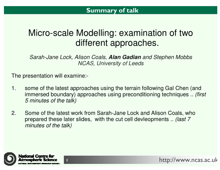
Micro-scale Modelling: examination of two different approaches. Sarah-Jane Lock, Alison Coals, Alan Gadian and Stephen Mobbs NCAS, University of Leeds The presentation will examine:- 1. some of the
Plan of Gillygate, York - Dashed outline defines the model domain. Two lamp-posts G3 and G4 are marked on the diagram
periodic domain,
grid-boxes: 231 x 261 x 60,
time: 1200 time steps,
model spin up ~ 30s - results computed
Rayleigh damping sponge above 50m Neutral, (constant potential
From Steppeler et al. (2006)