MELCOR Analysis on Effectiveness of Continuous Reactor Cavity - - PDF document

melcor analysis on effectiveness of continuous reactor
SMART_READER_LITE
LIVE PREVIEW

MELCOR Analysis on Effectiveness of Continuous Reactor Cavity - - PDF document

Transactions of the Korean Nuclear Society Virtual Spring Meeting July 9-10, 2020 MELCOR Analysis on Effectiveness of Continuous Reactor Cavity Flooding during Molten Corium-Concrete Interaction in OPR1000 Chang Hyun Song, Hoichul Jung, Sung


slide-1
SLIDE 1

MELCOR Analysis on Effectiveness of Continuous Reactor Cavity Flooding during Molten Corium-Concrete Interaction in OPR1000

Chang Hyun Song, Hoichul Jung, Sung Joong Kim* Department of Nuclear Engineering, Hanyang university 222 Wangsimni-ro, Seongdong-gu, Seoul 04763, Republic of Korea *Corresponding Author: sungjkim@hanyang.ac.kr

  • 1. Introduction

If Molten Corium-Concrete Interaction (MCCI)

  • ccurs after Reactor Pressure Vessel (RPV) failure, the

integrity of containment building may not be guaranteed due to concrete ablation and corresponding overpressure by a large amount of concrete decomposition gas. In

  • rder to mitigate the postulated MCCI, coolant injection

to reactor cavity is considered as the most effective mitigation strategy. This is because cooling the corium through coolant could be a most practical and prompt measure that can delay the concrete ablation [1]. However, if overlying coolant does not remove sufficient heat transferred from the corium, additional pressurization may occur by steam generation in the reactor cavity. Therefore, it is necessary to consider the

  • verpressure of the containment simultaneously. It was

expected that pressurization of the containment could be reduced through continuous coolant injection into the reactor cavity. If cold coolant is continuously injected, the coolant temperature can be maintained below the saturation temperature, under which steam generation can be reduced. On the other hand, the combustion risk is likely to be increased by higher mole fraction of hydrogen in containment building because of lower mole fraction of

  • steam. This tendency may vary depending on mass flow

rate of coolant injection. Therefore, this study analyzed the effectiveness of the continuous coolant injection strategy using MELCOR code. Based on the aforementioned consideration, the

  • verpressure

and hydrogen combustion risk in containment building were analyzed according to the mass flow rate of coolant into the reactor cavity. The Optimized Pressurized Reactor 1000 (OPR1000) was selected as a reference nuclear power plant (NPP). Because the cavity flooding system (CFS) is not designed for the OPR1000, a viable option to apply the coolant injection into the cavity is through continuous In- Vessel Injection (IVI). To realize this strategy, it was assumed that the injected coolant in RPV flowed into the reactor cavity through break region of the RPV.

  • 2. Methodology

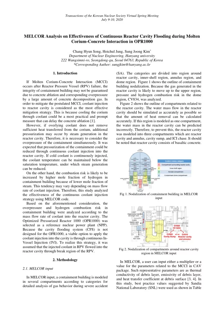
2.1. MELCOR input In MELCOR input, a containment building is modeled in several compartments according to categories for detailed analysis of gas behavior during severe accident (SA). The categories are divided into region around reactor cavity, inner-shell region, annulus region, and dome region. Figure 1 shows the outline of containment building nodalization. Because the gas generated in the reactor cavity is likely to move up to the upper region, pressure and hydrogen combustion risk in the dome region, CV834, was analyzed. Figure 2 shows the outline of compartments related to the reactor cavity. The water mass flow in the reactor cavity should be simulated as accurately as possible so that the amount of heat removal can be calculated

  • accurately. If this region is modeled as one compartment,

the water mass in the reactor cavity can be predicted

  • incorrectly. Therefore, to prevent this, the reactor cavity

was modeled into three compartments which are reactor cavity and annulus, cavity sump, and ICI chase. It should be noted that reactor cavity consists of basaltic concrete.

Fig 1. Nodalization of containment building in MELCOR input Fig 2. Nodalization of compartments around reactor cavity region in MELCOR input

In MELCOR, a user can input either a multiplier or a value for the parameters related to the MCCI in CAV

  • package. Such representative parameters are as thermal

conductivity of debris layer, emissivity of debris layer, and heat transfer coefficient at debris surface [3, 4]. In this study, best practice values suggested by Sandia National Laboratory (SNL) were used as shown in Table

Transactions of the Korean Nuclear Society Virtual Spring Meeting July 9-10, 2020

slide-2
SLIDE 2

1 [2]. These were derived through State-Of-the-Art Reactor Consequence Analysis (SOARCA) project. Through sensitivity analysis on the input parameters performed separately, it was confirmed that using the best practice values is the most conservative in evaluating heat transfer to both concrete and overlying coolant.

Table 1. SNL best practice value for input parameters related to MCCI in MELCOR CAV package [3]

Parameter Description Input value

Boiling Treatment of enhancements to the boiling curve 10.0 (multiplier) EMISS.OX Emissivity of the oxide phase 0.6 EMISS.MET Emissivity of the metal phase 0.6 EMISS.SUR Emissivity of the surroundings 0.6 HTRBOT Treatment of debris-to-surface heat transfer at the bottom surface 0.0 (multiplier) HTRSIDE Treatment of debris-to-surface heat transfer at the radial surface of the debris STANDARD HTRINT Treatment of debris-to-surface heat transfer at interior interfaces between debris layers STANDARD COND.OX Thermal conductivity of oxidic mixtures 1.0 (multiplier) COND.MET Thermal conductivity of metallic mixtures 1.0 (multiplier) COND.CRUST Conductivity in a solid (crust) sublayer in contact with water 3.0 (multiplier)

2.2. Accident scenario Initial accidents were selected as Station Blackout (SBO) accident and Large Break of Loss of Coolant Accident (LBLOCA), whose break size of cold leg is 6.06inch. In LBLOCA, it was assumed that High Pressure Safety Injection (HPSI), Low Pressure Safety Injection (LPSI), and Containment Spray System (CSS) were not operated as the conservative SBO accident

  • implies. Therefore, only safety injection (SI) from Safety

Injection Tank (SIT) and Passive Safety Valve (PSV) were operated considering their passive characteristics. In Tables 2 and 3, the major accident sequences for each accident were summarized respectively for the SBO and LBLOCA. External coolant is injected through the RPV upper plenum, which is the IVI. In actual accident situation, mitigation strategies are implemented at least 30 minutes after entry of severe accident (SA). For a more conservative analysis, the start of IVI was assumed 2hours after the entry of SA. As a result, in both scenarios, IVI began after RPV failure.

Table 2. Major accident sequence of SBO

Event Time [hr]

Accident start RCP trip Reactor trip Entry of SA 2.26 Cladding oxidation 2.28 Core dryout 2.66 Cladding melt 2.70 RPV failure 4.01 SIT injection 4.06 Start of IVI 4.26 SIT exhaust 4.35

Table 3. Major accident sequence of LBLOCA

Event Time [hr]

Accident start RCP trip Reactor trip SIT injection 0.08 SIT exhaust 0.22 Entry of SA 0.64 Cladding oxidation 0.68 Cladding melt 0.85 Core dryout 0.94 RPV failure 1.66 Start of IVI 2.64

2.3. Simulation matrix Four cases of mass flow rate of IVI were considered for each scenario as shown in Table 4. Temperature of the external injection coolant was assumed to be conservatively 322 K.

Table 4. Simulation matrix for each scenario

Case Mass flow rate [kg/s] Initial coolant temperature [K]

Case 1 (100gpm) 4.68 322 Case 2 (200gpm) 9.36 322 Case 3 (300gpm) 14.04 322 Case 4 (400gpm) 18.72 322

  • 3. Result and discussion

Figures 3 and 4 show mass of water in the reactor cavity for each accident. In both scenarios, it could be

  • bserved that water is present in the reactor cavity before

RPV failure. In the case of SBO, primary coolant is released through the PSV so that water exists in the reactor cavity. For LBLOCA, primary coolant discharged through the cold leg break is transferred to the reactor cavity. Because the mass of coolant of the SIT is included, the mass is relatively larger than the observed in SBO case. Through this, therefore, it is confirmed that both scenarios satisfy the pre-flooding condition.

Transactions of the Korean Nuclear Society Virtual Spring Meeting July 9-10, 2020

slide-3
SLIDE 3

Figure 3. Water mass in reactor cavity of SBO Figure 4. Water mass in reactor cavity of LBLOCA

Figure 5 shows water temperature and saturation temperature according to injection flow rate in SBO. In the early stage of MCCI, it is observed that evaporation

  • f water continues. Thereafter, continuous coolant

injection causes water temperature to decrease lower than saturation temperature at a certain time so that water is not vaporized any more. The low injection rate could not remove heat sufficiently so that vaporization continued until 72 hrs. On the other hand, in case of high injection rate, vaporization stopped promptly. LBLOCA results showed the similar trend to the SBO results. Figures 6 and 7 show concrete ablation depth along the direction in SBO. Because cooling of corium proceeds under pre-flooding condition, additional cooling effect by external injection was insignificant although water temperature is much lower. In addition, the sensitivity of heat removal of corium on the flow rate was not high. Therefore, it was judged that MELCOR underestimates the effect of reduction of water temperature. Likewise, the same trend was observed in LBLOCA case.

Fig 5. Water temperature and saturation temperature

  • f SBO

Figure 6. Axial concrete ablation depth of SBO Figure 7. Radial concrete ablation depth of SBO

Figures 8 and 9 show containment building pressure measured in the dome region. Pressure rise in the containment building could be significantly reduced by continuous injection of a large amount of coolant. Figures 10 and 11 show mole fractions of hydrogen in the containment building. Relative mole fraction of hydrogen increases with decreasing water evaporation. However, it is still much smaller than ignition criteria for hydrogen combustion which is 10% in MELCOR. Additionally, the same values were shown for other compartments in the containment building. Therefore, the results confirmed that overpressure in the containment building could be prevented through continuous external coolant injection.

Transactions of the Korean Nuclear Society Virtual Spring Meeting July 9-10, 2020

slide-4
SLIDE 4

Fig 8. Containment building pressure of SBO Fig 9. Containment building pressure of LBLOCA Fig 10. Mole fraction of hydrogen in dome region of SBO Fig 11. Mole fraction of hydrogen in dome region of LBLOCA

  • 4. Conclusions

To mitigate the MCCI, coolant injection to the reactor cavity is considered as the most common mitigation

  • strategy. However, additional pressurization may occur

by steam generation owing to the evaporation of injected

  • coolant. Based on this consideration, it was expected that

pressurization could be reduced through continuous coolant injection into the reactor cavity. Therefore, this study analyzed trend of pressure and hydrogen risk according to the flow rate of coolant injection for SBO and LBLOCA accident. The major findings in this study can be summarized as follows. (1) Pre-flooding condition was satisfied before RPV failure because primary coolant is released into the containment cavity in both accidents. Additional cooling effect by external injection was insignificant although water temperature is much lower than the observed in case without external injection. In addition, the sensitivity of heat removal on the flow rate was not high. Therefore, it was judged that MELCOR underestimates the effect of water temperature reduction. (2) Due to external injection, water stops vaporizing at a certain time. This is because water temperature in the reactor cavity becomes lower than saturation temperature. However, it is necessary to confirm whether there is an available external water source to inject a high flow rate

  • continuously. On the other hand, mole fraction of

hydrogen in containment building increased due to decrease of steam generation. (3) Large injection flow rate could effectively reduce pressure in containment building. In addition, increase in hydrogen concentration was not large so that mole fraction of hydrogen was much lower than ignition criterion. However, there is a possibility of ignition by spark even at low hydrogen concentration conditions. REFERENCES

[1] Kim, J. H., Kwon, S., Choi, J., & Cho, Y. J. (2019). Concrete ablation analysis for molten corium-concrete interaction mitigation strategy. Annals of Nuclear Energy, 132, 615–627. [2] OECD/NEA. (2017). State-of-the-Art Report on Molten- Corium-Concrete interaction and Ex-Vessel Molten-Core

  • Coolability. (NEA/CSNI/R(2016)15).

[3] L.L. Humphries, R.K. Cole, D.L. Louie, V.G. Figueroa, M.

  • F. Y. (2015). MELCOR Computer Code Manuals Vol. 1:

Primer and Users’ Guide. [4] L.L. Humphries, R.K. Cole, D.L. Louie, V.G. Figueroa, M.

  • F. Y. (2015). MELCOR Computer Code Manuals Vol. 2:

Reference Manual. Transactions of the Korean Nuclear Society Virtual Spring Meeting July 9-10, 2020