
SLIDE 1
1
YASKAWA ELECTRIC CORPORATION
Matrix Converter
The future has arrived
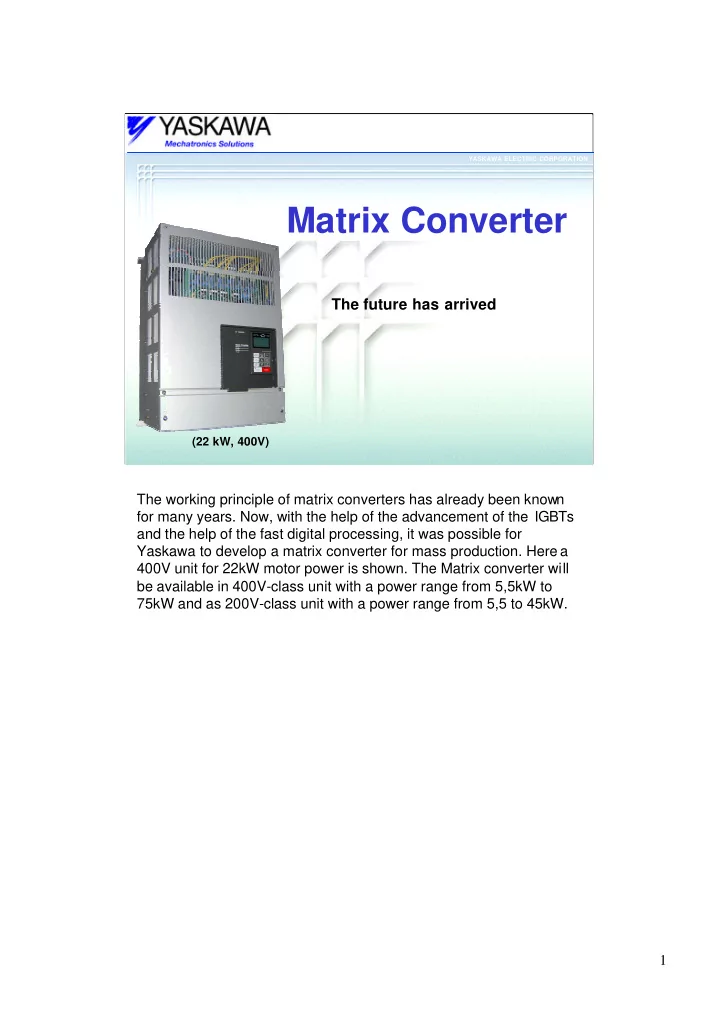
(22 kW, 400V)
The working principle of matrix converters has already been known for many years. Now, with the help of the advancement of the IGBTs and the help of the fast digital processing, it was possible for Yaskawa to develop a matrix converter for mass production. Here a 400V unit for 22kW motor power is shown. The Matrix converter will be available in 400V-class unit with a power range from 5,5kW to 75kW and as 200V-class unit with a power range from 5,5 to 45kW.