Manipulation 2 Overview, Concepts, Types Homework 2 out Project - - PDF document

manipulation
SMART_READER_LITE
LIVE PREVIEW

Manipulation 2 Overview, Concepts, Types Homework 2 out Project - - PDF document

3/3/20 Bookkeeping Manipulation 2 Overview, Concepts, Types Homework 2 out Project milestone 1 due right after spring break Make sure you make arrangements with your group for spring break A little tiny bit of stern stuff: Do not


slide-1
SLIDE 1

3/3/20 1

Manipulation

Overview, Concepts, Types

Many slides adapted from: en.wikipedia.org

  • S. N. Kale, Assistant Professor, PVPIT, Budhgaon

www.amci.com/tutorials/tutorials-stepper-vs-servo.asp www.modmypi.com/blog/whats-the-difference-between-dc-servo-stepper-motors

1

2 2

§ Homework 2 out § Project milestone 1 due right after spring break § Make sure you make arrangements with your

group for spring break

§ A little tiny bit of stern stuff:

§ Do not let 1-2 people do all the building. § Do not do anything to mess up your group.

Bookkeeping

2

3 3

1.

Build!

§

No soldering, plenty of instructions

§

Everyone should participate!

2.

Get working under ROS

3.

Wall following

4.

Soccer (this is the fun part)

§

Localization, data tracking, planning, sensors, …

5.

Tournament/demos

6.

Unbuild L

Project plans

3

4 4

§ How a robot:

§ Makes physical changes to the world around it § Physically interacts with the world and other agents

§ Moving/joining/reshaping/painting/etc. objects § Grasping, pushing, carrying, dropping, throwing,

lifting, …

§ Us

Using a manipulator (usually an arm) wi with some so sort o

  • f e

end-ef effect ector

What is Manipulation?

slide adapted from www.cs.columbia.edu/~allen/F15/NOTES/graspingClass2_2.ppt

4

5 5

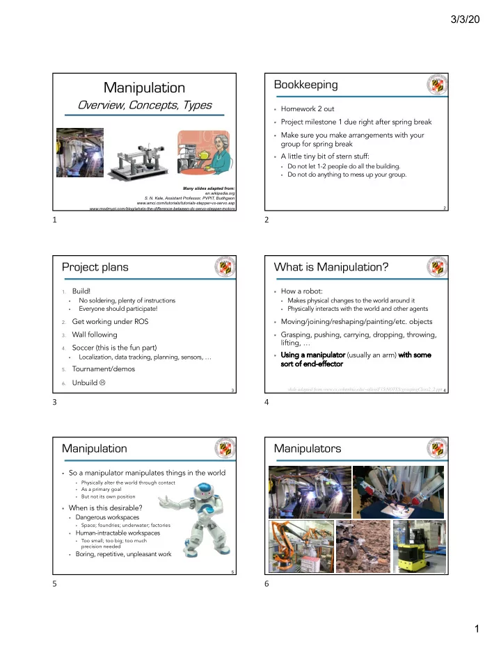
§ So a manipulator manipulates things in the world

§

Physically alter the world through contact

§

As a primary goal

§

But not its own position § When is this desirable?

§ Dangerous workspaces

§

Space; foundries; underwater; factories

§ Human-intractable workspaces

§

Too small; too big; too much precision needed

§ Boring, repetitive, unpleasant work

Manipulation

5

6 6

Manipulators

6

slide-2
SLIDE 2

3/3/20 2

8 8

Manipulators

8

9 9

Manipulators

9

10 10

§ Current

§ Industrial

§

Welding

§

Drilling

§

Attaching (screws, rivets)

§

Painting

§

Loading/unloading

§ Surgery § Space exploration § Chores § Patient care § Delivery

Uses

u Future

u Elder care u Entertainment u Environment sampling u Compliant-material

interactions (sewing)

u Police work

u Plus: more chores, more

patient care, more surgery, more space, &c. (but better)

10

11 11

Pick-and-Place

www.youtube.com/watch?v=wg8YYuLLoM0

11

12 12

§ Kinematic model: modeled as a chain of rigid

links connected by joints

§ Actuator

§ Generates motion or force; usually a motor

§ End Effector

§ Device at the end of an arm; interacts

with environment

§ Grippers, tools

§ Actuation

§ How are parts made to move?

Terminology

Links Joints End Effector (gripper)

12

14 14

§ Kinematic model: modeled as a chain of rigid

links connected by joints

§ Li

Link nks: unjointed length of robot

§ Jo

Joint nts: produce translational or rotational movement

§

Dofs: how many to describe joint’s position and orientation in space?

§ Sliding or jointed

§ Manipulator

§ Gripper, tool, sensor… § Also “end effector”

Kinematic Models

Links Joints End Effector (gripper)

14

slide-3
SLIDE 3

3/3/20 3

15 15

§ By drive type § By actuation: Tendons,

direct servoing, underactuation

§ By motion type

§ Prismatic (linear) § Revolute (rotational)

§ By Characteristics

§ Payload, radius,

Working area

Manipulator Characterization

15

16 16

§ Prismatic: sliding / translational § Revolute: rotational

Joints

16

17 17

Actuators

Hydraulic Motor Stepper Motor Pneumatic Motor Servo Motor Pneumatic Cylinder DC Motor

17

18 18

§ Hydraulic/pneumatic

§ Heavy loads, high speeds § Sometimes hard to control (esp. pneumatic) § Doesn’t produce sparks

When Do We Use…

Hydraulic Motor Pneumatic Motor Pneumatic Cylinder

18

19 19

§ Most common robotic actuators use

combinations of electro-mechanical devices

§ Stepper motor

§

Subdivides a rotation into 4-10 increments

§

Open Loop

§ Servo Motor

§

Closed loop

§

Subdivides a rotation arbitrarily

§

AC servo motor

§

Brushless DC servo motor

§

Brushed DC servo motor § But usually motors.

When Do We Use…

19

21 21

§ A kinematic chain of rigid links connected by joints

§ “Ki

Kinematics is the branch of classical mechanics which describes the motion of objects and groups of objects.”

§ Prismatic (denoted P)

§ Sliding / translational /

linear; allows a linear relative motion between 2 links

§ Revolute (denoted R)

§ Rotational; allows relative

rotation between two links

Kinematics: P(rismatic) & R(evolute)

Sp Spong ng, H , Hutchinson, , Vi

  • Vidyasagar. R

. Robot M Modeling a and C

  • Control. 2

. 2006.

21

slide-4
SLIDE 4

3/3/20 4

22 22

§ A joint represents a connection between two links § Denotation of re

relative displacement between links

§ θ for revolute joint § d for prismatic joint

§ Denotation of axis of motion

§ zi between link i and link i+1: § Axis of rotation of a revolute joint § Axis of translation of a prismatic joint

Joints: Denotation

Sp Spong ng, H , Hutchinson, , Vi

  • Vidyasagar. R

. Robot M Modeling a and C

  • Control. 2

. 2006.

22

23 23

§ Co

Configuration

§ Specifies location of every point on manipulator

§ How?

§ Links are rigid § Base is (assumed to be) fixed § So just need values for the joint variables

§

Angle for R joints (θ), offset for P joints (d) § Manip. configuration ≣ a set of values for joint

variables

§ Set of all possible configurations is the

co conf nfigur uration n space. ce.

Configuration Space

Spong, Hutchinson, Vidyasagar. Robot Modeling and Control. 2006.

Links Base

23

26 26 § What’s a link? § What’s a joint? § What’s a base? § What kinds of joint

are there?

§ What’s a configuration? § How is it specified? § What’s an end effector?

Sanity check

§ A rigid, connecting piece § Where two links move relative

to each other

§ The robot’s “starting point” –

furthest from end effector

§ Revolute and prismatic § Current orientation and

position of manipulator

§ Per joint, using θ or d § The interactive bit on the end

26

27 27

§ A system has n DoFs if exactly n parameters are

required to completely specify the configuration.

§ For a manipulator:

§ Configuration can be specified by n joint parameters § # of DoFs = dimension of the configuration space § So, # number of joints determines DoFs

§ Rigid object in 3D space has six parameters

§ 3 positioning (x, y, z), 3 orientation (roll, pitch and yaw)

§ DoFs < 6 ⇒ arm cannot reach every point in

workspace wi with arbitrary orientation

DoFs for Manipulation

Sp Spong ng, H , Hutchinson, , Vi

  • Vidyasagar. R

. Robot M Modeling a and C

  • Control. 2

. 2006.

27

28 28

§ DoFs < 6 ⇒ arm cannot reach every point in

workspace with arbitrary orientation

§ Sometimes you need more

§ E.g., dealing with obstacles

§ DoFs > 6: ki

kinem nematica cally re redundant

§ Difficulty of control problem as # DoFs grows?

§ Increases rapidly with the number of links

§

Every 2 links need a joint

§ Control 1/Maneuverability

Notes on DoFs

Sp Spong ng, H , Hutchinson, , Vi

  • Vidyasagar. R

. Robot M Modeling a and C

  • Control. 2

. 2006. Eh Ehsan Re Rezapou

  • ur.

. Pe Pettersen, , Gr Gravdahl, , Li Liljebäck, , Ke

  • Kelasidi. R

. Robotics a and Bi

  • Biomimetics. 2

. 2014.

28

29 29

S.

  • S. N. Kale,

e, Assistant nt Profes essor, PVPIT, Bu Budhgaon

Common Configurations

29

slide-5
SLIDE 5

3/3/20 5

30 30

u So this is?

RRR Articulated

S.

  • S. N. Kale,

e, Assistant nt Profes essor, PVPIT, Bu Budhgaon

Configuration Example

30

31 31

Spong, Hutchinson, Vidyasagar. Robot Modeling and Control. 2006.

RPY: Spherical Joint

Zero length links

31

32 32

Yaw

S.

  • S. N. Kale,

e, Assistant nt Profes essor, PVPIT, Bu Budhgaon

RPY: Whole joint

32

33 33

S.

  • S. N. Kale,

e, Assistant nt Profes essor, PVPIT, Bu Budhgaon Sp Spong ng, H , Hutchinson, , Vi

  • Vidyasagar. R

. Robot M Modeling a and C

  • Control. 2

. 2006.

§ Link specification + joint specification

§ Configuration space can be de

derived d from kinematic model

§ How joint movement relates to link motion § Assumptions:

§ Desired state of the robot can be specified by

changes to joints

§ Any set of joint states can be specified § When specified, the links will execute as instructed

Kinematic Model

33

34 34

Configuration Spaces

§ Co

Configuration: location of all points on a manipulator at a point in time

§ Specified by state of every joint (θ or d) § Can treat these as a ve

vect ctor, q

§ Example: if θ1=60˚, d1=3cm, and θ2=12.2° (ß RPR)! § q = <q1, q2, q3,> = <60, 3, 12.2>

§ Co

Configuration space: set of all possible configurations

§ Doesn’t say anything about dynamics.

§ How is it moving? How CAN it move?

This is also called joint space

34

35 35

§ St

State: e: manipulator’s configuration plus dynamics (its movement) plus inputs (commands)

§ Sufficient to determine any future state of the

manipulator

§ St

State e space: ce: set of all possible states

§ Specification: joint variables q, joint velocities q

§ Acceleration is derived from joint velocities

§ States represented as a vector x = (q, q) § And that’s it for dynamics for now!

State Spaces

. .

35

slide-6
SLIDE 6

3/3/20 6

36 36

§ So where can a

manipulator go (reach in space)?

§ Wo

Workspace:

§ Set of all possible

po positions of end effector

§ In practice, these can be

complex

Workspaces

Spong, Hutchinson, Vidyasagar. Robot Modeling and Control. 2006. engineerjau.wordpress.com/2013/07/07/on-the-basis-of-workspaces-of-robotic-manipulators-part-1

Kinematic model Workspace

36

37 37

Kinematic model Workspace § De

Dexterous workspace: end effector can be in any position an and or

  • rientat

ation

  • n

§ Subset of workspace

Workspaces 2

Spong, Hutchinson, Vidyasagar. Robot Modeling and Control. 2006. engineerjau.wordpress.com/2013/07/07/on-the-basis-of-workspaces-of-robotic-manipulators-part-1

37

38 38

§ Ac

Accuracy: how close is manipulator to specified configuration/is end effector to specified coordinate?

§ Re

Repeat atab ability: how similar is behavior given an identical command?

§ We only measure joint state (using encoders)

§ Everything else is inferred from rigid links

§ Primary source of failure: Ri

Rigidity of

  • f links

§ And straightness, but that can be calibrated out

§ Given gravity, load, angular velocity, …

Measuring Success

38

39 39

§ Payload: How much can it lift?

§ Varies depending on location of end effector

§ Speed: How fast can it go?

§ How does speed of a joint relate to speed of arm?

§ Working radius: what’s the boundary it can’t

reach past?

§ Actuation type: How is it made to go?

§ Servo, tendon-driven, underactuated, …

Other Important Features

39

40 40

§ Kinematic model: Links, joints, and base § Configuration space: arrangement of a

manipulator

§ I.e., where are all its parts?

§ State space: Configuration + motion § Workspace: where it can reach, in what

configuration

§ Accuracy, repeatability/precision

Summary: Specifying Manipulators

40