
SLIDE 1
Linear Arrays
Chapter 7
- 1. Basics for the linear array
computational model.
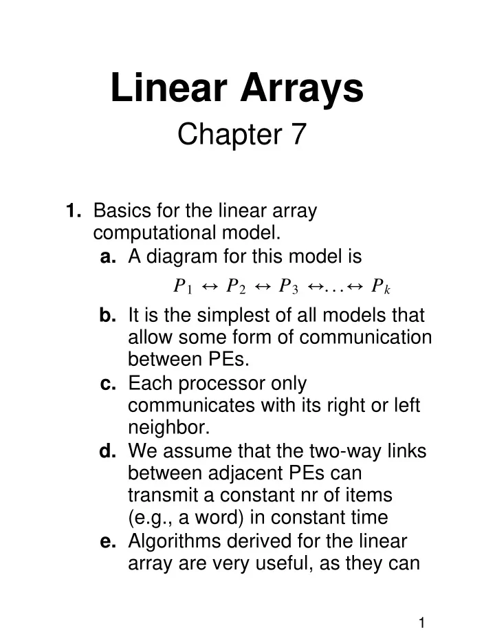
- a. A diagram for this model is
P1 ↔ P2 ↔ P3 ↔...↔ Pk
- b. It is the simplest of all models that
allow some form of communication between PEs.
- c. Each processor only
communicates with its right or left neighbor.
- d. We assume that the two-way links
between adjacent PEs can transmit a constant nr of items (e.g., a word) in constant time
- e. Algorithms derived for the linear
array are very useful, as they can
1