Lecture 14: UML State Machines 2016-06-30 Prof. Dr. Andreas - - PDF document

lecture 14 uml state machines
SMART_READER_LITE
LIVE PREVIEW

Lecture 14: UML State Machines 2016-06-30 Prof. Dr. Andreas - - PDF document

Softwaretechnik / Software-Engineering Lecture 14: UML State Machines 2016-06-30 Prof. Dr. Andreas Podelski, Dr. Bernd Westphal Albert-Ludwigs-Universitt Freiburg, Germany 14 2016-06-30 main Topic Area Architecture &


slide-1
SLIDE 1

– 14 – 2016-06-30 – main –

Softwaretechnik / Software-Engineering

Lecture 14: UML State Machines

2016-06-30

  • Prof. Dr. Andreas Podelski, Dr. Bernd Westphal

Albert-Ludwigs-Universität Freiburg, Germany

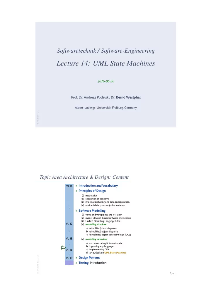
Topic Area Architecture & Design: Content

– 14 – 2016-06-30 – Sblockcontent –

2/38

  • Introduction and Vocabulary
  • Principles of Design

(i) modularity (ii) separation of concerns (iii) information hiding and data encapsulation (iv) abstract data types, object orientation

  • Software Modelling

(i) views and viewpoints, the 4+1 view (ii) model-driven/-based software engineering (iii) Unified Modelling Language (UML) (iv) modelling structure a) (simplified) class diagrams b) (simplified) object diagrams c) (simplified) object constraint logic (OCL) (v) modelling behaviour a) communicating finite automata b) Uppaal query language c) implementing CFA d) an outlook on UML State Machines

  • Design Patterns
  • Testing: Introduction

VL 11 . . . VL 12 . . . VL 13 . . . VL 14 . . . VL 15 . . .

slide-2
SLIDE 2

Content

– 14 – 2016-06-30 – Scontent –

3/38

  • CFA at Work continued
  • design checks and verification
  • Uppaal architecture
  • case study
  • CFA vs. Software
  • a CFA model is software
  • implementing CFA
  • Recall MDSE
  • UML State Machines
  • Core State Machines
  • steps and run-to-completion steps
  • Hierarchical State Machines
  • Rhapsody
  • UML Modes

Design Sanity Check: Drive to Configuration

– 14 – 2016-06-30 – Scfaatworkrest –

4/38

  • Question: Is is (at all) possible to have no water in the vending machine model?

(Otherwise, the design is definitely broken.)

  • Approach: Check whether a configuration satisfying

w = 0 is reachable, i.e. check NVM | = ∃♦ w = 0. for the vending machine model NVM.

slide-3
SLIDE 3

Design Check: Scenarios

– 14 – 2016-06-30 – Scfaatworkrest –

5/38

  • Question: Is the following existential LSC satisfied by the model?

(Otherwise, the design is definitely broken.)

LSC: buy tea AC: true AM: initial I: permissive User Coin Validator Choice Panel C50 C50 C50 TEA ¬E1!

  • Approach: Use the following newly created CFA ‘Scenario’

end_of_scenario TEA! C50! C50! C50!

instead of User and check whether location end_of_scenario is reachable, i.e. check N ′

VM |

= ∃♦ Scenario.end_of_scenario. for the modified vending machine model N ′

VM.

Design Verification: Invariants

– 14 – 2016-06-30 – Scfaatworkrest –

6/38

  • Question: Is it the case that the “tea” button is only enabled

if there is e 1.50 in the machine?

(Otherwise, the design is broken.)

  • Approach: Check whether the implication

tea_enabled = ⇒ CoinValidator.have_c150 holds in all reachable configurations, i.e. check NVM | = ∀ tea_enabled imply CoinValidator.have_c150 for the vending machine model NVM.

drink_ready have_c150 have_e1 have_c100 have_c50 idle OK? OK? OK? OK? E1? tea_enabled := (t > 0) C50? water_enabled := (w > 0), tea_enabled := (t > 0) C50? tea_enabled := (t > 0) E1? soft_enabled := (s > 0) C50? soft_enabled := (s > 0) C50? water_enabled := (w>0)

slide-4
SLIDE 4

Design Verification: Sanity Check

– 14 – 2016-06-30 – Scfaatworkrest –

7/38

  • Question: Is the “tea” button ever enabled?

(Otherwise, the considered invariant tea_enabled = ⇒ CoinValidator.have_c150 holds vacuously.)

  • Approach: Check whether a configuration satisfying water_enabled = 1 is reachable.

Exactly like we did with w = 0 earlier.

Design Verification: Another Invariant

– 14 – 2016-06-30 – Scfaatworkrest –

8/38

  • Question: Is it the case that, if there is money in the machine

and water in stock, that the “water” button is enabled?

  • Approach: Check

NVM | = ∀ (CoinValidator.have_c50 or CoinValidator.have_c100 or CoinValidator.have_c150) imply water_enabled.

drink_ready have_c150 have_e1 have_c100 have_c50 idle OK? OK? OK? OK? E1? tea_enabled := (t > 0) C50? water_enabled := (w > 0), tea_enabled := (t > 0) C50? tea_enabled := (t > 0) E1? soft_enabled := (s > 0) C50? soft_enabled := (s > 0) C50? water_enabled := (w>0)

slide-5
SLIDE 5

Recall: Universal LSC Example

– 14 – 2016-06-30 – Scfaatworkrest –

9/38

LSC: buy water AC: true AM: invariant I: strict User CoinValidator ChoicePanel Dispenser C50 pWATER

¬(C50! ∨ E1! ∨ pSOFT! ∨ pTEA! ∨ pFILLUP!)

water_in_stock dWATER OK

¬(dSoft! ∨ dTEA!)

Uppaal Architecture

– 14 – 2016-06-30 – Suppaalarch –

10/38

server verifyta

yes/no/don’t know

.xml .trc .q

C++ Java

slide-6
SLIDE 6

Case Study: Wireless Fire Alarm System

– 14 – 2016-06-30 – Scfawfas –

11/38

(Arenis et al., 2014) Components

Jammer Switcher gBlockedChannel gOSensor / gORepeater

Media . . . Master

Frame Window

Timers

SlotTimer RX Channels TX Channels FrameTimer

. . .

errorDetected channel ChanRot channelLZ, ...

  • !"!#$

!%

  • $!

&

  • &

$! '!"$ !"'!"$ ' ("!'!"$ % !"!#$ !) $*! !' !"!#$ !"!

  • + !%

* ",-. + !"! + + !) * ",-. + !"! * ",-. +% !"!

(R1) The loss of the ability of the system to transmit a signal from a component to the central unit is detected in less than 300 seconds [...].

  • i∈C (⌈FAIL = i ∧ ¬DETi⌉ =

⇒ ℓ ≤ 300s)

(R2) A single alarm event is displayed at the central unit within 10 seconds.

  • i∈C⌈ ALARM{i} ⌉ =

⇒ (⌈ALARMi ∧ ¬DISPi⌉ = ⇒ ℓ ≤ 10s) ,

Content

– 14 – 2016-06-30 – Scontent –

12/38

  • CFA at Work continued
  • design checks and verification
  • Uppaal architecture
  • case study
  • CFA vs. Software
  • a CFA model is software
  • implementing CFA
  • Recall MDSE
  • UML State Machines
  • Core State Machines
  • steps and run-to-completion steps
  • Hierarchical State Machines
  • Rhapsody
  • UML Modes
slide-7
SLIDE 7

CFA vs. Software

– 14 – 2016-06-30 – main –

13/38

A CFA Model Is Software

– 14 – 2016-06-30 – Scfasw –

14/38

  • Definition. Software is a finite description S of a (possibly infinite)

set S of (finite or infinite) computation paths of the form σ0

α1

− → σ1

α2

− → σ2 · · · where

  • σi ∈ Σ, i ∈ N0, is called state (or configuration), and
  • αi ∈ A, i ∈ N0, is called action (or event).

The (possibly partial) function · : S → S is called interpreta- tion of S.

  • Let C(A1, . . . , An) be a network of CFA.
  • Σ = Conf
  • A = Act
  • C = {π =

ℓ0, ν0

λ1

− − → ℓ1, ν1

λ2

− − → ℓ2, ν2

λ3

− − → · · · | π is a computation path of C}.

  • Note: the structural model just consists of the set of variables and the locations of C.
slide-8
SLIDE 8

Model-Driven Software Engineering

– 14 – 2016-06-30 – Smdse –

16/38

  • (Jacobson et al., 1992): “System development is model building.”
  • Model driven software engineering (MDSE): everything is a model.
  • Model based software engineering (MBSE): some models are used.

Idea Structure Declarative Behaviour

  • Declarative

Behaviour′

  • Structure′

Constructive Behaviour

  • Structure′′

Constructive Behaviour′

  • Implementation

elicit refine refine refine refine

requirements model requirements/ constraints design system model | =? | =?

generate/ program

slide-9
SLIDE 9

Implementing CFA

– 14 – 2016-06-30 – Simpl –

17/38

  • Now that we have a CFA model C(A1, . . . , An) (thoroughly checked using Uppaal),

we would like to have software — an implementation of the model.

  • This task can be split into two sub-tasks:

(i) implement each CFA Ai in the model by module SAi, (ii) implement the communication in the network by module SC.

(This has, by now, been provided implicitly by the Uppaal simulator and verifier.)

SC A1 A2 ... An

calls

Example

– 14 – 2016-06-30 – Simpl –

18/38

W0 dispense Wi FILLUP? w := 3 FILLUP? w := 3 w == 0 DOK! w > 0 DOK! DWATER? w := w - 1

slide-10
SLIDE 10

Example

– 14 – 2016-06-30 – Simpl –

18/38

W0 dispense Wi FILLUP? w := 3 FILLUP? w := 3 w == 0 DOK! w > 0 DOK! DWATER? w := w - 1

int w := 3; typedef {Wi, dispense, W0} st_T; st_T st := Wi; SetAct take_action( Act α ) { SetAct R := ∅; if st = Wi : if α = DWATER? : w := w − 1; st := dispense; if (w = 0) R := R ∪ {DOK!}; if (w > 0) R := R ∪ {DOK!}; α = FILLUP? : w := 3; st := Wi; R := R ∪ {FILLUP?, DWATER?}; fi; st = dispense : if α = DOK! ∧ w = 0 : st := W0; R := R ∪ {FILLUP?}; α = DOK! ∧ w > 0 : st := Wi; R := R ∪ {FILLUP?}; fi; st = W0 : if α = FILLUP? : w := 3; st := Wi; R := R ∪ {FILLUP?, DWATER?}; fi; fi; return R; }

Translation Scheme. . .

– 14 – 2016-06-30 – Simpl –

19/38 ... for A = ({ℓ1, . . . , ℓm}, B, {v1, . . . , vk}, E, ℓini) with

E = {(ℓ1, α1,1, ϕ1,1, r1,1, ℓ′

1,1), . . . , (ℓ1, α1,n1, ϕ1,n1,

r1,n1, ℓ′

1,n1),

. . . (ℓm, αm,1, ϕm,1, rm,1, ℓ′

m,1), . . . , (ℓm, αm,nm, ϕm,nm,

rm,nm, ℓ′

m,nm)} :

T1 v1 := v1,ini; ...Tk vk := vk,ini; typedef {ℓ1, . . . , ℓm} st_T; st_T st := ℓini; SetAct take_action( Act α ) { SetAct R := ∅; if . . . st = ℓi : if . . . α = αi,j ∧ ϕi,j : ri,j; st := ℓ′

i,j;

if (ℓ′

i,j = ℓ1 ∧ ϕ1,1) R := R ∪ {α1,1};

. . . if (ℓ′

i,j = ℓm ∧ ϕm,nm) R := R ∪ {αm,nm};

. . . fi; . . . fi; return R; }

slide-11
SLIDE 11

Deterministic CFA

– 14 – 2016-06-30 – Simpl –

20/38

  • Definition. A network of CFA C with (joint) alphabet B is called deterministic if

and only if each reachable configuration has at most one successor configuration, i.e. if ∀ c ∈ Conf (C) reachable ∀ λ ∈ B!? ∪ {τ} ∀ c1, c2 ∈ Conf (C) • c

λ

− → c1 ∧ c

λ

− → c2 = ⇒ c1 = c2.

  • Proposition. Whether C is deterministic is decidable.
  • Proposition. If C is deterministic, then the translation of C is a deterministic program.

Putting It All Together

– 14 – 2016-06-30 – Simpl –

21/38

  • Let N = C(A1, . . . , An) with pairwise disjoint variables.
  • Assume B = Binput ˙

∪ Binternal, where Binput are dedicated input channels, i.e. there is no edge with action a! and a ∈ Binput.

  • Then software SN consists of SA1, . . . , SAn and the following SC.

SetAct R1 := R1,ini, ..., Rn := Rn,ini ; / / initially enabled actions void main() { do true : if true : (α, snd, rcv) := select(R1, . . . , Rn); / / choose synchronisation / / (rcv = 0 if α = τ, / / blocks on deadlock) true : (α, snd, rcv) := read_input(); / / or read input (snd = 0) fi for (k =1 to n) if (snd = k) Rk := take_actionk(α); / / sender for (k =1 to n) if (rcv = k) Rk := take_actionk(¯ α); / / receiver / / snapshot

  • d

}

slide-12
SLIDE 12

Model vs. Implementation

– 14 – 2016-06-30 – Simpl –

22/38

  • Define SN to be the set of computation paths σ0

α1

− − → σ1

α2

− − → σ2 · · · such that σi has the values at ‘snapshot’ at the i-th iteration and αi is the i-th action.

  • Then SN bisimulates T (C(A0, A1, . . . , An)) where A0 has one location ℓ and edges

E0 = {(ℓ, α!, true, , ℓ) | α ∈ Binput}.

FILLUP! C50! WATER! half_idle water_selected have_c50 idle DWATER! DOK? WATER? C50? W0 dispense Wi FILLUP? w := 3 FILLUP? w := 3 w == 0 DOK! w > 0 DOK! DWATER? w := w - 1

  • Yes, and...?
  • If Uppaal reports that NVM |

= ∃♦ w = 0 holds, then w = 0 is reachable in SNVM.

  • If Uppaal reports that

NVM | = ∀ tea_enabled imply CoinValidator.have_c150 holds, then SNVM is correspondingly safe.

slide-13
SLIDE 13

Model-Driven Software Engineering

– 14 – 2016-06-30 – Smdse –

23/38

  • (Jacobson et al., 1992): “System development is model building.”
  • Model driven software engineering (MDSE): everything is a model.
  • Model based software engineering (MBSE): some models are used.

Idea Structure Declarative Behaviour

  • Declarative

Behaviour′

  • Structure′

Constructive Behaviour

  • Structure′′

Constructive Behaviour′

  • Implementation

elicit refine refine refine refine

requirements model requirements/ constraints design system model | =? | =?

generate/ program

Content

– 14 – 2016-06-30 – Scontent –

24/38

  • CFA at Work continued
  • design checks and verification
  • Uppaal architecture
  • case study
  • CFA vs. Software
  • a CFA model is software
  • implementing CFA
  • Recall MDSE
  • UML State Machines
  • Core State Machines
  • steps and run-to-completion steps
  • Hierarchical State Machines
  • Rhapsody
  • UML Modes
slide-14
SLIDE 14

UML State Machines

– 14 – 2016-06-30 – main –

25/38

UML Core State Machines

– 14 – 2016-06-30 – Sumlstm –

26/38

C D

x : Int = 27 itsD 0..1 itsC 0..1

  • signal
  • E
  • signal
  • F
  • signal
  • G

s1 s2

E/itsD ! F G

s1 s2

F[x > 0]

s3

/itsC ! G /x := 0 annot ::=

  • event[. event]∗
  • trigger

[ [ guard ] ] [ / action]

  • with
  • event ∈ E,

(optional)

  • guard ∈ ExprS

(default: true, assumed to be in ExprS )

  • action ∈ ActS

(default: skip, assumed to be in ActS )

slide-15
SLIDE 15

Event Pool and Run-To-Completion

– 14 – 2016-06-30 – Sumlstm –

27/38 s1 s2

E/itsD ! F G

s1 s2

F[x > 0]

s3

/itsC ! G /x := 0

u1 : C u2 : D x = 27

itsD itsC

u1 u2 step state stable x state stable event pool s1 1 27 s1 1 E ready for u1

Event Pool and Run-To-Completion

– 14 – 2016-06-30 – Sumlstm –

27/38 s1 s2

E/itsD ! F G

s1 s2

F[x > 0]

s3

/itsC ! G /x := 0

u1 : C u2 : D x = 27

itsD itsC

u1 u2 step state stable x state stable event pool s1 1 27 s1 1 E ready for u1 1 s2 1 27 s1 1 F ready for u2

slide-16
SLIDE 16

Event Pool and Run-To-Completion

– 14 – 2016-06-30 – Sumlstm –

27/38 s1 s2

E/itsD ! F G

s1 s2

F[x > 0]

s3

/itsC ! G /x := 0

u1 : C u2 : D x = 27

itsD itsC

u1 u2 step state stable x state stable event pool s1 1 27 s1 1 E ready for u1 1 s2 1 27 s1 1 F ready for u2 2 s2 1 27 s2 3 s2 1 27 s3 G ready for u1

Event Pool and Run-To-Completion

– 14 – 2016-06-30 – Sumlstm –

27/38 s1 s2

E/itsD ! F G

s1 s2

F[x > 0]

s3

/itsC ! G /x := 0

u1 : C u2 : D x = 27

itsD itsC

u1 u2 step state stable x state stable event pool s1 1 27 s1 1 E ready for u1 1 s2 1 27 s1 1 F ready for u2 2 s2 1 27 s2 3 s2 1 27 s3 G ready for u1 4.a s2 1 s1 1 G ready for u1 5.a s1 1 s1 1 4.b s1 1 27 s3 5.b s1 1 s1 1

slide-17
SLIDE 17

Rhapsody Architecture

– 14 – 2016-06-30 – Sumlstm –

28/38

C.h D.h C.cpp D.cpp MainDefaultComponent.cpp

DfltCmp.exe

generate build / make (compiler) run

Rhapsody Architecture

– 14 – 2016-06-30 – Sumlstm –

28/38

C.h D.h C.cpp D.cpp MainDefaultComponent.cpp

DfltCmp.exe

generate build / make (compiler) run E! go

“D just stepped from s1 to s2 by transition t”

slide-18
SLIDE 18

Composite (or Hierarchical) States

– 14 – 2016-06-30 – Sumlstm –

29/38

  • OR-states, AND-states Harel (1987).
  • Composite states are about abbreviation, structuring, and avoiding redundancy.

n

  • w

e s resigned X/ X/ X/ X/

  • n
  • w

e s resigned X/ n fastN

  • w

fastW e fastE s fastS F/ F/

  • n
  • w

e s

  • slow

fast F/ F/

Example

– 14 – 2016-06-30 – Sumlstm –

30/38

Idle waitOK have_c100_or_e1> have_c100 have_e1 have_c150> have_c50> drinkReady Idle waitOK have_c100_or_e1> have_c100 have_e1 have_c150> have_c50> drinkReady E1/itsChanger

  • >giveback_100()

C50/itsChoicePanel

  • >enable_Water();

E1/ itsChanger

  • >giveback_100()

C50 C50/ itsChanger

  • >giveback_50()

C50 E1/itsChoicePanel->enableSoft(); E1 C50 OK Entry Action: itsChoicePanel

  • >enable_Water();

Entry Action: itsChoicePanel

  • >enable_Soft();

Entry Action: itsChoicePanel

  • >enable_Tea();

Tea_selected Inactive Soft_selected Water_selected Request_sent Tea_selected Inactive Soft_selected Water_selected Request_sent TEA[Tea_enabled] /itsDrinkDispenser

  • >GEN(DTEA)

/itsDrinkDispenser

  • >GEN(DSOFT);

if (itsCoinValidator

  • >IS_IN(have_c150))

itsChanger->giveback_50(); WATER[Water_enabled] /disable_all(); SOFT[Soft_enabled] /itsDrinkDispenser

  • >GEN(DWATER);

if (itsCoinValidator->IS_IN(have_c150)) itsChanger->giveback_100(); else if (itsCoinValidator->IS_IN(have_c100)) itsChanger->giveback_50();

  • n
  • n

T2 Tea_out T1 T3 S2 Soft_out S1 S3 W2 Water_out W1 W3 FillingUp

  • n

T2 Tea_out T1 T3 S2 Soft_out S1 S3 W2 Water_out W1 W3 FillingUp DTEA/ Prepare_Tea(); itsCoinValidator

  • >GEN(OK);

DTEA/ Prepare_Tea(); itsCoinValidator

  • >GEN(OK);

DTEA/ Prepare_Tea(); itsCoinValidator

  • >GEN(OK);

DSOFT/ Prepare_Soft(); itsCoinValidator

  • >GEN(OK);

DSOFT/ Prepare_Soft(); itsCoinValidator

  • >GEN(OK);

DSOFT/ Prepare_Soft(); itsCoinValidator

  • >GEN(OK);

DWATER/ Prepare_Water(); itsCoinValidator

  • >GEN(OK);

DWATER/ Prepare_Water(); itsCoinValidator

  • >GEN(OK);

DWATER/ Prepare_Water(); itsCoinValidator

  • >GEN(OK);

FILLUP/itsCoinValidator

  • >update_ChoicePanel();
slide-19
SLIDE 19

Would be Too Easy. . .

– 14 – 2016-06-30 – Sumlstm –

31/38

  • s1

s2

  • s3

s8 s4

  • s5

s6

E/ F/ F/ E/ G/

s7 [true]/ F/ → “Software Design, Modelling, and Analysis with UML” in the winter semester.

UML Modes

– 14 – 2016-06-30 – main –

32/38

slide-20
SLIDE 20

UML and the Pragmatic Attribute

– 14 – 2016-06-30 – Sumlmode –

33/38

Recall: definition “model” (Glinz, 2008, 425): (iii) the pragmatic attribute, i.e. the model is built in a specific context for a specific purpose. Examples for context/purpose: Floorplan as sketch: Floorplan as blueprint: Floorplan as program: +

wiringplan

+

windows

+

...

With UML it’s the Same [http://martinfowler.com/bliki]

– 14 – 2016-06-30 – Sumlmode –

34/38

The last slide is inspired by Martin Fowler, who puts it like this: “[...] people differ about what should be in the UML because there are differing fundamental views about what the UML should be. I came up with three primary classifications for thinking about the UML: UmlAsSketch, UmlAsBlueprint, and UmlAsProgrammingLanguage. ([...] S. Mellor independently came up with the same classifications.) So when someone else’s view of the UML seems rather different to yours, it may be because they use a different UmlMode to you.” Claim:

  • This not only applies to UML as a language (what should be in it etc.?),
  • but at least as well to each individual UML model.
slide-21
SLIDE 21

With UML it’s the Same [http://martinfowler.com/bliki]

– 14 – 2016-06-30 – Sumlmode –

34/38

The last slide is inspired by Martin Fowler, who puts it like this: “[...] people differ about what should be in the UML because there are differing fundamental views about what the UML should be. I came up with three primary classifications for thinking about the UML: UmlAsSketch, UmlAsBlueprint, and UmlAsProgrammingLanguage. ([...] S. Mellor independently came up with the same classifications.) So when someone else’s view of the UML seems rather different to yours, it may be because they use a different UmlMode to you.” Claim:

  • This not only applies to UML as a language (what should be in it etc.?),
  • but at least as well to each individual UML model.

Sketch In this UmlMode developers use the UML to help communicate some aspects of a system. [...] Sketches are also useful in documents, in which case the focus is communication ra- ther than completeness. [...] The tools used for sketching are lightweight drawing tools and

  • ften people aren’t too

particular about keeping to every strict rule of the UML. Most UML diagrams shown in books, such as mine, are sketches. Their emphasis is on selective communication rather than complete specification. Hence my sound-bite “compre- hensiveness is the enemy of comprehensibility” Blueprint [...] In forward engineering the idea is that blueprints are developed by a designer whose job is to build a detailed design for a programmer to code up. That design should be sufficiently complete that all design decisions are laid out and the programming should follow as a pretty straightforward activity that requires little thought. [...] Blueprints require much more sophisticated tools than sketches in order to handle the details required for the task. [...] Forward engineering tools sup- port diagram drawing and back it up with a repository to hold the

  • information. [...]

ProgrammingLanguage If you can detail the UML enough, and provide semantics for everything you need in software, you can make the UML be your programming language. Tools can take the UML diagrams you draw and compile them into executable code. The promise of this is that UML is a higher level language and thus more productive than current programming languages. The question, of course, is whether this promise is true. I don’t believe that graphical programming will succeed just because it’s graphical. [...]

UML-Mode of the Lecture: As Blueprint

– 14 – 2016-06-30 – Sumlmode –

35/38

  • The “mode” fitting the lecture best is AsBlueprint.

Goal:

  • be precise to avoid misunderstandings.
  • allow formal analysis of consistency/implication
  • n the design level — find errors early.

Yet we tried to be consistent with the (informal semantics) from the standard documents OMG (2007a,b) as far as possible.

Plus:

  • Being precise also helps to work in mode AsSketch:

Knowing “the real thing” should make it easier to (i) “see” which blueprint(s) the sketch is supposed to denote, and (ii) to ask meaningful questions to resolve ambiguities.

slide-22
SLIDE 22

Tell Them What You’ve Told Them. . .

– 14 – 2016-06-30 – Sttwytt –

36/38

  • We can use tools like Uppaal to
  • check and verify CFA design models against requirements.
  • CFA (and state charts)
  • can easily be implemented using the translation scheme.
  • Wanted: verification results carry over to the implementation.
  • if code is not generated automatically,

verify code against model.

  • UML State Machines are
  • principally the same thing as CFA,

yet provide more convenient syntax.

  • Semantics uses
  • asynchronous communication,
  • run-to-completion steps

in contrast to CFA.

(We could define the same for CFA, but then the Uppaal simulator would not be useful any more.)

  • Mind UML Modes.

References

– 14 – 2016-06-30 – main –

37/38

slide-23
SLIDE 23

References

– 14 – 2016-06-30 – main –

38/38 Arenis, S. F., Westphal, B., Dietsch, D., Muñiz, M., and Andisha, A. S. (2014). The wireless fire alarm system: Ensuring conformance to industrial standards through formal verification. In Jones, C. B., Pihlajasaari, P., and Sun, J., editors, FM 2014: Formal Methods - 19th International Symposium, Singapore, May 12-16, 2014. Proceedings, volume 8442 of LNCS, pages 658–672. Springer. Glinz, M. (2008). Modellierung in der Lehre an Hochschulen: Thesen und Erfahrungen. Informatik Spektrum, 31(5):425–434. Harel, D. (1987). Statecharts: A visual formalism for complex systems. Science of Computer Programming, 8(3):231–274. Jacobson, I., Christerson, M., and Jonsson, P. (1992). Object-Oriented Software Engineering - A Use Case Driven

  • Approach. Addison-Wesley.

Ludewig, J. and Lichter, H. (2013). Software Engineering. dpunkt.verlag, 3. edition. OMG (2007a). Unified modeling language: Infrastructure, version 2.1.2. Technical Report formal/07-11-04. OMG (2007b). Unified modeling language: Superstructure, version 2.1.2. Technical Report formal/07-11-02.