last lecture summary chapter 5 the data link layer
play

Last Lecture: Summary Chapter 5: The Data Link Layer Goals: - PDF document

Last Lecture: Summary Chapter 5: The Data Link Layer Goals: Overview: Our goals: network layer services understand principles understand principles behind data link layer IP addressing behind network layer services: services:


  1. Last Lecture: Summary Chapter 5: The Data Link Layer Goals: Overview: Our goals: ¸ network layer services ¸ understand principles ¸ understand principles behind data link layer ¸ IP addressing behind network layer services: services: ¸ routing principle: path selection o error detection, correction o routing (path ¸ IP selection) o sharing a broadcast channel: multiple access ¸ hierarchical routing o dealing with scale o link layer addressing ¸ Internet routing protocols o how a router works o reliable data transfer, flow control: done! reliable transfer o advanced topics: IPv6, ¸ instantiation and implementation of various link intra-domain o multicast layer technologies inter-domain o ¸ instantiation and ¸ what’s inside a router? implementation in ¸ IPv6 the Internet ¸ multicast routing 7/10 Datakommunikation & Internet, Anders Broberg, UmU Link layer 1 7/10 Datakommunikation & Internet, Anders Broberg, UmU Link layer 2 Chapter 5 outline 
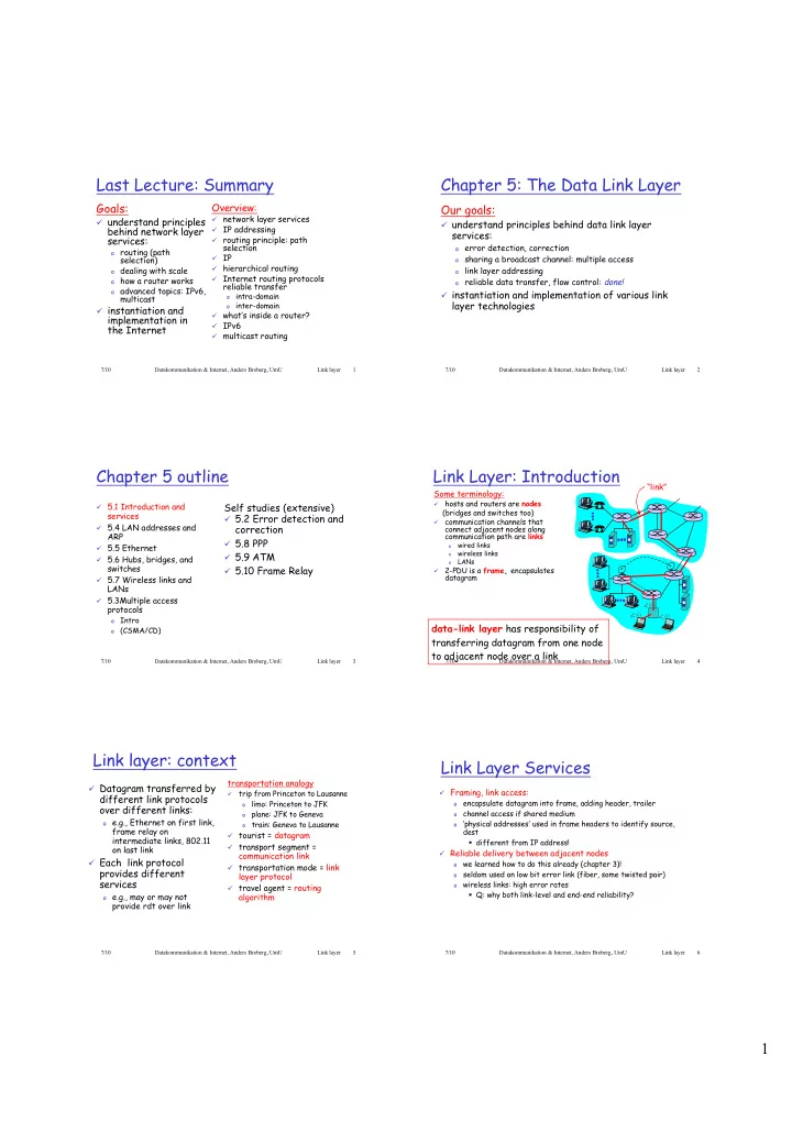
Link Layer: Introduction “link” Some terminology: hosts and routers are nodes ¸ 5.1 Introduction and Self studies (extensive) ¸ (bridges and switches too) services ¸ 5.2 Error detection and communication channels that ¸ ¸ 5.4 LAN addresses and correction connect adjacent nodes along ARP communication path are links ¸ 5.8 PPP wired links ¸ 5.5 Ethernet o wireless links ¸ 5.9 ATM o ¸ 5.6 Hubs, bridges, and LANs o switches ¸ 5.10 Frame Relay 2-PDU is a frame, encapsulates ¸ datagram ¸ 5.7 Wireless links and LANs ¸ 5.3Multiple access protocols Intro o data-link layer has responsibility of (CSMA/CD) o transferring datagram from one node to adjacent node over a link 7/10 Datakommunikation & Internet, Anders Broberg, UmU Link layer 3 7/10 Datakommunikation & Internet, Anders Broberg, UmU Link layer 4 Link layer: context Link Layer Services transportation analogy ¸ Datagram transferred by ¸ Framing, link access: trip from Princeton to Lausanne ¸ different link protocols encapsulate datagram into frame, adding header, trailer limo: Princeton to JFK o o over different links: plane: JFK to Geneva channel access if shared medium o o o e.g., Ethernet on first link, ‘physical addresses’ used in frame headers to identify source, train: Geneva to Lausanne o o frame relay on dest ¸ tourist = datagram intermediate links, 802.11 ß different from IP address! ¸ transport segment = on last link ¸ Reliable delivery between adjacent nodes communication link ¸ Each link protocol we learned how to do this already (chapter 3)! o ¸ transportation mode = link provides different seldom used on low bit error link (fiber, some twisted pair) layer protocol o services wireless links: high error rates o ¸ travel agent = routing ß Q: why both link-level and end-end reliability? o e.g., may or may not algorithm provide rdt over link 7/10 Datakommunikation & Internet, Anders Broberg, UmU Link layer 5 7/10 Datakommunikation & Internet, Anders Broberg, UmU Link layer 6 1

  2. Link Layer Services (more) Adaptors Communicating datagram rcving link layer protocol ¸ Flow Control: sending node pacing between adjacent sending and receiving nodes o node frame frame ¸ Error Detection : errors caused by signal attenuation, noise. o adapter adapter receiver detects presence of errors: o ¸ link layer implemented in ¸ receiving side ß signals sender for retransmission or drops frame “adaptor” (aka NIC) o looks for errors, rdt, flow ¸ Error Correction: o Ethernet card, PCMCI control, etc receiver identifies and corrects bit error(s) without resorting o card, 802.11 card o extracts datagram, passes to retransmission ¸ sending side: to rcving node ¸ Half-duplex and full-duplex o encapsulates datagram in ¸ adapter is semi- with half duplex, nodes at both ends of link can transmit, but o a frame not at same time autonomous o adds error checking bits, rdt, flow control, etc. ¸ link & physical layers 7/10 Datakommunikation & Internet, Anders Broberg, UmU Link layer 7 7/10 Datakommunikation & Internet, Anders Broberg, UmU Link layer 8 Chapter 5 outline LAN Addresses and ARP 5.1 Introduction and services Self studies (extensive) 32-bit IP address: ¸ 5.4 LAN addresses and ARP ¸ ¸ 5.2 Error detection and ¸ network-layer address 5.5 Ethernet ¸ correction ¸ used to get datagram to destination IP network (recall IP 5.6 Hubs, bridges, and ¸ network definition) ¸ 5.8 PPP switches LAN (or MAC or physical or Ethernet) address: 5.7 Wireless links and LANs ¸ ¸ 5.9 ATM ¸ used to get datagram from one interface to another physically- 5.3Multiple access protocols ¸ ¸ 5.10 Frame Relay connected interface (same network) Intro o (CSMA/CD) ¸ 48 bit MAC address (for most LANs) o burned in the adapter ROM 7/10 Datakommunikation & Internet, Anders Broberg, UmU Link layer 9 7/10 Datakommunikation & Internet, Anders Broberg, UmU Link layer 10 LAN Addresses and ARP LAN Address (more) Each adapter on LAN has unique LAN address ¸ MAC address allocation administered by IEEE ¸ manufacturer buys portion of MAC address space (to assure uniqueness) ¸ Analogy: (a) MAC address: like Social Security Number (b) IP address: like postal address ¸ MAC flat address => portability can move LAN card from one LAN to another o ¸ IP hierarchical address NOT portable depends on IP network to which node is attached o 7/10 Datakommunikation & Internet, Anders Broberg, UmU Link layer 11 7/10 Datakommunikation & Internet, Anders Broberg, UmU Link layer 12 2

  3. ARP: Address Resolution Protocol Recall earlier routing discussion Starting at A, given IP ¸ Each IP node (Host, Router) A Question: how to determine datagram addressed to B: 223.1.1.1 on LAN has ARP table MAC address of B ¸ look up net. address of B, find B 223.1.2.1 ¸ ARP Table: IP/MAC address 223.1.1.2 on same net. as A mappings for some LAN knowing B’s IP address? 223.1.2.9 223.1.1.4 nodes ¸ link layer send datagram to B B 223.1.2.2 < IP address; MAC address; TTL> inside link-layer frame E 223.1.1.3 223.1.3.27 TTL (Time To Live): time o after which address 223.1.3.1 223.1.3.2 mapping will be forgotten frame source, datagram source, (typically 20 min) dest address dest address A’s IP B’s MAC A’s MAC B’s IP IP payload addr addr addr addr datagram frame 7/10 Datakommunikation & Internet, Anders Broberg, UmU Link layer 13 7/10 Datakommunikation & Internet, Anders Broberg, UmU Link layer 14 Routing to another LAN ARP protocol walkthrough: send datagram from A to B via R assume A know’s B IP address A wants to send datagram to ¸ A caches (saves) IP-to- ¸ B, and A knows B’s IP address. MAC address pair in its ARP table until information Suppose B’s MAC address is ¸ not in A’s ARP table. becomes old (times out) A broadcasts ARP query o soft state: information ¸ packet, containing B's IP that times out (goes address away) unless refreshed A all machines on LAN o ¸ ARP is “plug-and-play”: receive ARP query Two ARP tables in router R, one for each IP network (LAN) ¸ o nodes create their ARP B receives ARP packet, replies ¸ to A with its (B's) MAC tables without address R intervention from net B frame sent to A’s MAC administrator o ¸ In routing table at source Host, find router 111.111.111.110 address (unicast) ¸ In ARP table at source, find MAC address E6-E9-00-17-BB- 4B, etc 7/10 Datakommunikation & Internet, Anders Broberg, UmU Link layer 15 7/10 Datakommunikation & Internet, Anders Broberg, UmU Link layer 16 A creates datagram with source A, destination B ¸ Chapter 5 outline A uses ARP to get R’s MAC address for 111.111.111.110 ¸ A creates link-layer frame with R's MAC address as dest, frame ¸ contains A-to-B IP datagram A’s data link layer sends frame ¸ ¸ 5.1 Introduction and Self studies (extensive) R’s data link layer receives frame ¸ services ¸ 5.2 Error detection and R removes IP datagram from Ethernet frame, sees its destined to ¸ ¸ 5.4 LAN addresses and correction B ARP ¸ 5.8 PPP R uses ARP to get B’s physical layer address ¸ ¸ 5.5 Ethernet ¸ 5.9 ATM R creates frame containing A-to-B IP datagram sends to B ¸ ¸ 5.6 Hubs, bridges, and ¸ 5.10 Frame Relay switches ¸ 5.7 Wireless links and LANs A ¸ 5.3Multiple access protocols o Intro R o (CSMA/CD) B 7/10 Datakommunikation & Internet, Anders Broberg, UmU Link layer 17 7/10 Datakommunikation & Internet, Anders Broberg, UmU Link layer 18 3

Download Presentation
Download Policy: The content available on the website is offered to you 'AS IS' for your personal information and use only. It cannot be commercialized, licensed, or distributed on other websites without prior consent from the author. To download a presentation, simply click this link. If you encounter any difficulties during the download process, it's possible that the publisher has removed the file from their server.

Recommend


More recommend