Joint-less Industrial Floor, MTD Hungaria, Nemesvamos 1 General - - PowerPoint PPT Presentation

joint less industrial floor
SMART_READER_LITE
LIVE PREVIEW

Joint-less Industrial Floor, MTD Hungaria, Nemesvamos 1 General - - PowerPoint PPT Presentation

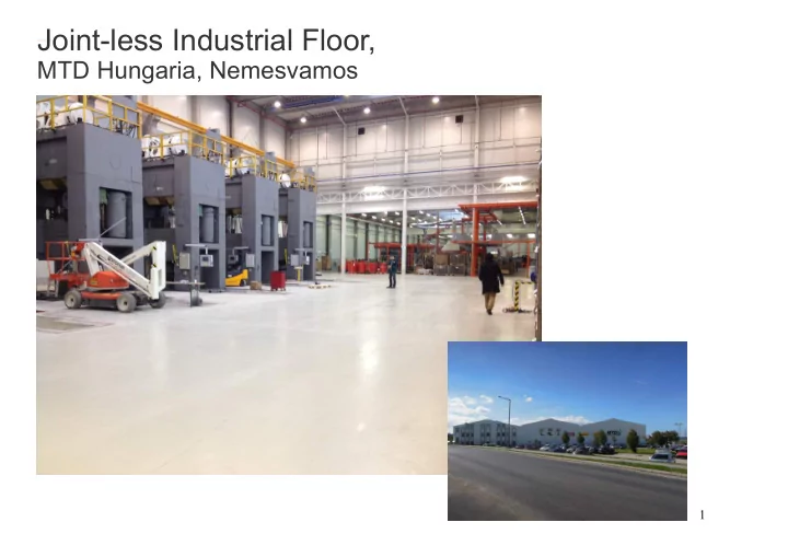
Joint-less Industrial Floor, MTD Hungaria, Nemesvamos 1 General Floor Characteristics Joint-less Industrial Floor made of Shrinkage-Compensating Concrete Joint-less : 'joint-less' doesn't mean that there are absolutely no joints in the floor.


slide-1
SLIDE 1

1

Joint-less Industrial Floor,

MTD Hungaria, Nemesvamos

slide-2
SLIDE 2

2

General Floor Characteristics

Joint-less Industrial Floor made of Shrinkage-Compensating Concrete Joint-less: 'joint-less' doesn't mean that there are absolutely no joints in the floor. However joint-less floors have 80-90% less joints than conventional floors. Joints: joints need to be formed at certain locations, e.g.: where daily concrete pour is finished (this is called construction joint), or at critical floor locations where stress needs to be reduced. These joints are steel armored to protect joint edges from spalling and the prefabricated joint profiles inculde plate dowels for effective load transfer between the floorpanels separated by the joint. Concrete: expansive concrete made with DENKA CSA #20, C30/37-XC1-32-F3 Subgrade: 35 cm crushed rock, E2=100-130 N/mm2 Floor thickness: 15 cm Load bearing capacity: 12 ton/rack leg; 15 ton/m2 Floor flatness and levelness: FF35/FL20

slide-3
SLIDE 3

3

Floor Design

Structural Design Industrial floors are multi-layered structures: Sub-soil Sub-grade Concrete slab For floor design sub-soil characteristics were taken into account, sub-grade and concrete slab was designed for the applied loads. Design criterium: concrete slab remains crack-free. Locating joints correctly is vital for crack free floors. The employed flooring technology allows 40 meter joint spacing without any cracks (as

  • pposed to 5-7 meter joint spacing, as in case of conventional flooring). Also, long and

narrow floor sections can be built without cracking.

slide-4
SLIDE 4

4

Floor Design

Joint locations (indicated by black arrows below)

slide-5
SLIDE 5

5

Floor Design

Joint formation Joint edges subjected to small hard wheels are prone to break (spall). Any joint wider than appr. 1 mm will spall. To avoid spalling we protect joint edges with steel (See below). Effective load transfer in joints is necessary to aviod step formation between the two sides

  • f the joint that would further deteriorate joint edges.
slide-6
SLIDE 6

6

Floor Design

Steel bar reinforcement Properly sized and located steel reinforcement is key to effective shrinkage

  • compensation. If shrinkage-compensating concrete is properly and elastically restrained,

it induces compressive stress in the slab that is intended to approximately offset the tendency of shrinkage to induce tensile stress. Taking into account the expansive potential of the concrete mix and the expected shrinkage, a small ratio of steel bar reinforcement was placed in the upper half of the slab. Additional reinforcement was employed around re-entrant corners to avoid cracks.

slide-7
SLIDE 7

Floor Design

Concrete mix design Shrinkage-compensating concrete expands after setting. The expansion takes place in the first 7 days. After 7 seven days -when subjected to drying- it starts shrinking. If designed properly expansion equals or it is slightly higher than the ultimate shrinkage. To confirm the above, the employed concrete mixture went under examination at the Budapest University of Technology and Economics for 28 days. The following properties have been looked at: Expansion (ASTM C878) Shrinkage Fresh concrete workability Slump loss over 1,5 hours

Length change

slide-8
SLIDE 8

8

Floor Construction

Steel bar reinforcement

slide-9
SLIDE 9

9

Floor Construction

Steel bar reinforcement at re-entrant corners

slide-10
SLIDE 10

10

Floor Construction

Joint formation: steel armored joint with effective load transfer

slide-11
SLIDE 11

11

Floor Construction

Joint formation: steel armored joint with effective load transfer

slide-12
SLIDE 12

12

Floor Construction

Pouring concrete

slide-13
SLIDE 13

13

Floor Construction

Pouring concrete

slide-14
SLIDE 14

14

Floor Construction

Pouring concrete

slide-15
SLIDE 15

15

Floor Construction

Pouring concrete

slide-16
SLIDE 16

16

Floor Construction

Dosing DENKA CSA #20 expansive agent at the ready mix concrete plant

slide-17
SLIDE 17

17

Floor Construction

Taking concrete sample at the ready mix concrete plant Fresh concrete quality was continously checked during construction. The followings were tested: Concrete temperature Slump flow Water content Concrete density

slide-18
SLIDE 18

18

Monitoring floor performance

Concrete expansion and shrinkage are measured with built in strain gauges Strain gauge Data acquisition system

slide-19
SLIDE 19

19

Results

No cracks No joint spalling Small joint opening

slide-20
SLIDE 20

20

Results

Floor performance data acquired by two built in strain gauges confirms that the floor behaves as expected:

slide-21
SLIDE 21

21

Results

(The floor recieved epoxy coating for oil resistance)

slide-22
SLIDE 22

22

Results

(The floor recieved epoxy coating for oil resistance)

slide-23
SLIDE 23

23

Results

(The floor recieved epoxy coating for oil resistance)

slide-24
SLIDE 24

24

Results

Joint

slide-25
SLIDE 25

25

Conclusions

With no cracks and no joints to maintain the floor is practically maintenance-free. No down times No maintenance cost No headache The floor next door is a conventional floor, with closely spaced joints (6 m). It is 6 months

  • ld and the joint deterioration typical of this kind of flooring already started and joint repair

will be needed soon.

slide-26
SLIDE 26

26

Thank you for chosing us!