
SLIDE 1
ION MOBILITY DRIFT TUB PAPRI CHAKRABORT 02.07.2016 What is Ion - - PowerPoint PPT Presentation
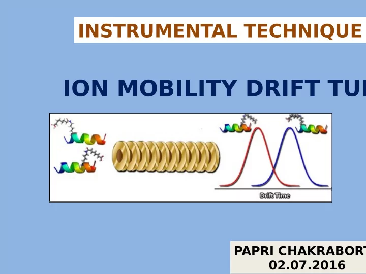
INSTRUMENTAL TECHNIQUE ION MOBILITY DRIFT TUB PAPRI CHAKRABORT 02.07.2016 What is Ion Mobility Spectrometry ? Ion-mobility spectrometry (IMS) is an analytical technique used to separate and identify ionized molecules in the gas phase based on
Ion-mobility spectrometry (IMS) is an analytical technique used to separate and identify ionized molecules in the gas phase based on their size,shape and charge, depending on their mobility in a carrier bufger gas.
IMS was fjrst developed primarily by Earl W. McDaniel of Georgia Institute of T echnology in the 1950s and 1960s when he used drift cells with low applied electric fjelds to study gas phase ion mobilities and reactions. In the following decades, he coupled his new technique with a magnetic- sector mass spectrometer, with others also utilizing his techniques in new
spectrometers and high-performance liquid chromatography setups.
Primarily, three IMS techniques are used in IM-MS: Drift time ion mobility spectrometry (DTIMS) T ravelling-wave ion mobility spectrometry (TWIMS) Field-asymmetric ion mobility spectrometry (FAIMS)
DTIMS TWIMS FAIMS
Francesco Lanucara et.al, Nature Chemistry. 2014, 6, 281-294
TWIMS DRIFT TUBE A TWIMS device comprises a series of ring electrodes called a stacked ring ion guide (SRIG), to which a travelling voltage is applied. These voltages radially confjne the ions, while application of a transient direct current (DC) voltage to each electrode in succession from one end
Radio-frequency voltages of opposite phases are applied to adjacent electrodes.
Schematic of ring electrodes in Drif
Radiofrequency Voltage Supply High Voltage DC Power Supply Segmented electrode Gate electrode Ring Electrode Ion Collector Resistor Capacitor Voltage Divider Disc Shaped Electrode Ion mobility spectrometer with high ion transmission effjciency US 200301 32379 A1 U+Vcos(ωt) U-Vcos(ωt) U, V are amplitudes of respe D.C. and R.F . sources RF sources frequency Ѡ ~ 10 kHz to 100 MHz
applied to a pair of adjacent rings, to produce a potential barrier that the ions cannot cross. As the DC potential is stepped to an adjacent set of rings the ion barrier moves forward, causing any ions in front of it to be propelled forwards.
the wave, the ions will get separated as more compact ions will move forward and less compact ions will roll over the wave.
Model traveling wave profjles: triangular (a), bitriangular(b), and half-sinusoidal (c).
80, 9689–9699
The physical quantity ion mobility K is defjned as the proportionality factor of an ion's drift velocity vd in a gas and an electric fjeld of strength E, Ion mobilities are commonly reported as a reduced mobilities, correcting to standard gas density n0, which can be expressed in standard temperature T0 = 273 K and standard pressure p0 = 1013 mbar : The ion mobility K can be experimentally determined by measuring the drift time tD of an ion traversing within a homogeneous electric fjeld, the potential difgerence U in the drift length L :
9689–9699
The recorded drift time of an ion allows calculation of Ω, according to the Mason –Schamp equation : The proportional relationship between Ω and K0 is only true at or below the ‘low-fjeld limit’, where the ratio between electric fjeld strength and bufger gas density is small. (≤ 2 × 10–17 V cm2). The TWIMS device is operated below the low-fjeld limit and, following calibration, determination of CCS is therefore possible. Calibration of the drift time through the TWIMS cell under defjned conditions (gas type/pressure, travelling wave speed or height, and so
longer applicable, owing to the constantly changing electric fjeld.
https://www.youtube.com/watch? v=LTLtLsgkgLY
A drift tube’s resolving power RP can be calculated as : where tD is the ion drift time, ΔtD is the Full width at half maximum. Pressure inside the drift tube is maintained around 0.025 – 3 mbar. Low pressure results in strong heating even at moderate E. Low gas pressure in TW IMS means strong fjelds in E/N terms and thus substantial heating of ions. This may cause fragmentation or distortion of macromolecular structures, complicating their detection and characterization. CCS determination requires calibration of the drift time through the TWIMS cell. Advantage of TWIMS is that it can be used for mobility separation of product ions generated either by collision induced dissociation or by electron-transfer dissociation. The geometric confjguration of current commercial DTIMS-MS and FAIMS – MS instruments means that they can only be used to separate analytes immediately post-ionization.
IMS Cell of Synapt G2-Si
thickness and 1.0 mm spacing