SLIDE 1
Introduction to Packet Tracer
What is Packet Tracer? Packet Tracer is a protocol simulator developed by Dennis Frezzo and his team at Cisco Systems. Packet Tracer (PT) is a powerful and dynamic tool that displays the various protocols used in networking, in either Real Time or Simulation mode. This includes layer 2 protocols such as Ethernet and PPP, layer 3 protocols such as IP, ICMP, and ARP, and layer 4 protocols such as TCP and UDP. Routing protocols can also be traced. Purpose: The purpose of this lab is to become familiar with the Packet Tracer interface. Learn how to use existing topologies and build your own. Requisite knowledge: This lab assumes some understanding of the Ethernet protocol. At this point we have not discussed other protocols, but will use Packet Tracer in later labs to discuss those as well. Version: This lab is based on Packet Tracer 4.0 Beta, Test1.
Introduction to the Packet Tracer Interface using a Hub Topology
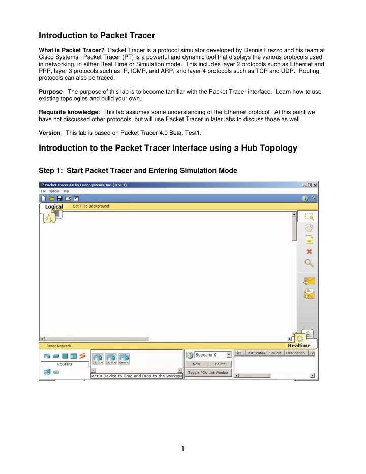
Step 1: Start Packet Tracer and Entering Simulation Mode 1
SLIDE 2 Step 2: Open an existing topology
Perform the following steps to open the 2c1.pkt topology. By default, the topology opens in Realtime
examine the difference between Realtime and Simulation modes in a moment. Help can be
using the Help
- menu. Both
- nline help one
each topic and tutorials are available. Please take advantage of this facilities. To view the IP address, subnet mask, default gateway, and MAC address of a host, move the cursor over that computer. Be sure the Select box is checked at the top of the tool box.
2
SLIDE 3 Viewing PC0 information using the Select tool: Once the file is
Simulation icon, to enter simulation
mode allows you to view the a sequence of events associated with the communications between two or more devices. Realtime mode performs the
- peration with all
- f the sequence of
events happening at “real time”.
3
SLIDE 4 Step 3: PC0 pinging PC1
For those not familiar with ping: We will examine pings and the ICMP protocol in much more detail later. The ping program generates an IP packet with an encapsulated ICMP Echo Request message. It is a tool used to test basic layer 2 and layer 3 communications between two devices. When the user issues the ping command, most operating systems send multiple (four or five) ICMP Echo messages. When the destination device receives the ping, Echo Request, it issues an Echo Reply. Command issued from PC0: ping 192.168.10.37 Packet Tracer allows us to either issue the command from the command prompt or to use the Add Simple PDU tool. We will look at both ways to do this. In order to view only the “pings”, in the Event List, click on ALL/NONE to clear all protocols, and then click
- n ICMP to select only that protocol.
2 1
Using the Simple PDU Tool One method for pinging a device from another device is to use the Simple PDU tool. This tool performs the ping without having to issue the ping command. Choose the Add Simple PDU tool from the tool box:
4
SLIDE 5 Click once on PC0, the device issuing the ping (ICMP Echo Request) and then click once on PC1 (the destination of the ICMP Echo Request). By clicking on the Capture/Forward button, this will forward each event. For example, the first event is the building of the ICMP packet and encapsulating it in an Ethernet frame. The next event will send this Ethernet frame from the Ethernet NIC in PC0 to the Hub. Continue to click on the Capture/Forward button and watch the ICMP Echo Requests and ICMP Echo
- Replies. Notice that the hub floods all of the frames out all ports except the port incoming port.
Normally, before the ICMP Echo Request, ping, is sent out by PC0, an ARP Request might first be sent. We will discuss this later, but we disabled the display of ARP in the Event List earlier. Note: Using this tool, only a single ping, ICMP Echo Request is sent by PC0, instead of the four pings when using the command prompt. When the ICMP Echo Request and ICMP Echo Reply is finished, you will receive the following message:
5
SLIDE 6 Step 4: Viewing the frame (Protocol Analyzer)
To examine the actual protocols being sent, click on the colored Info box in the Event List. The Event List shows where this Ethernet Frame is currently, “At Device”, the previous devices, “Last Device”, and the type
- f information encapsulated in the Ethernet Frame, “Info”.
Single click on the first event’s Info box to view the Ethernet frame with the encapsulated IP Packet and the encapsulated ICMP message “At Device” PC0. The PDU (Protocol Data Unit) is displayed in two different formats, OSI Model and Outbound PDU Details. View them both, paying particular attention to the Layer 2 Ethernet frame. We will discuss IP and ICMP later. The default is the OSI Model view with a brief description with what is occurring with this packet. Click on the Outbound PDU Details tab to see the protocol details including the layer 2 Ethernet frame, the layer 3 IP packet and ICMP message.
6
SLIDE 7
Looking at the Switch Algorithm and Switch MAC Address Tables
Step 1: Open the following topology Open the file 3s1.pkt Notice that it is similar to the previous topology, but the layer 1 hub has been replace with a layer 2 switch. Click on the Simulation icon to switch to simulation mode.
7
SLIDE 8 Use the Select tool to view IP address and MAC address information for the various hosts.. Step 2: Viewing the Switch MAC Address Table Use the Inspect tool to view the MAC Address Table
The MAC Address Table is empty as it has not learned any Source Ethernet MAC Addresses. Notice that there is also a VLAN column in this table. This will be discussed in future courses.
8
SLIDE 9 Waiting for Spanning Tree Protocol (STP) Note: Because of how Packet Tracer also simulates the Spanning Tree Protocol (later), at times the switch may show amber lights on its interfaces. To correct this, click the Realtime mode icon, wait for the lights to turn green, and then click the Simulation mode icon, returning to where you left off. Step 3: Setting the Event List Protocols and Viewing the MAC Address Table Set the Event List Filters to include both ICMP and ARP. We need to include the display of ARP to better examine how the switch MAC Address Table gets updated. (more later) If you haven’t done so already, use the Inspect tool to view the MAC Address Table
9
SLIDE 10
Step 3: Issuing a Ping and Viewing the MAC Address Table Using the Add Simple PDU perform a ping from PC0 to PC1. Choose the Add Simple PDU tool from the tool box: This is the same as doing: Click once on PC0, the device issuing the ping (ICMP Echo Request) and then click once on PC1 (the destination of the ICMP Echo Request). ARP Request Before PC0 can send the ICMP Echo Request, ping, it needs to send an ARP Request. We will talk about this later, but an ARP (Address Resolution Protocol) Request is how a host that knows the Destination IP Address of a device discovers the Ethernet Destination MAC Address for that same device. (more later) So, the ICMP Echo Request, ping is put on hold, stored in memory and an ARP Request is transmitted first.
10
SLIDE 11
To view the ARP Request, click on the Info box in the Event List. Notice the Destination MAC Address is a broadcast, 48 1 bits or 12 Hexadecimal Fs. Click the Capture/Forward button to advance to the next event, the ARP Request going from PC0 to the switch. Notice that the switch’s MAC Address Table is updated with the Source MAC Address of PC0 and the incoming port number. ARP Request
11
SLIDE 12
The packet is flooded out all ports because the Destination MAC Address of an ARP Request is a broadcast (48 1 bits or all F’s in Hex). ARP Request ARP Reply PC2 and PC3 ignore the ARP Request because PC0 is only asking for the owner of the IP Address 172.16.1.2 to reply. PC1 now sends back an ARP Reply with its MAC Address. (Again, this will be discussed later.) This time the switch updates its MAC Address Table with the Ethernet Source MAC Address of PC1 and the incoming port number. ARP Reply
12
SLIDE 13
If you want to view the protocol details of the ARP Reply, click on the Info box in the Event List.
13
Continue to click on the Capture/Forward button until the ARP Reply reaches PC0. Because the ARP Reply is encapsulated in an Ethernet frame with a unicast Destination MAC Address and that MAC Address is in the switch’s MAC Address Table, the switch filters the frame by only sending it out Port FastEthernet0/1. ARP Reply
SLIDE 14
Ping: ICMP Echo Request PC0 now has the Destination MAC Address for PC1’s IP Address, so it can now send out the ICMP Echo Request, ping.
14
If you want to view the protocol details of the ICMP Echo Request, click on the Info box in the Event List. Notice that the Destination MAC Address is a unicast. ICMP Echo Request, ping
SLIDE 15
The switch has the Source MAC Address in its table so it resets the 5 minute timer. The switch also has the Destination MAC address in its table so it filters the frame by forwarding it out of only port FastEthernet0/2. ICMP Echo Request, ping Ping: ICMP Echo Reply PC1 returns an ICMP Echo Reply. ICMP Echo Reply, ping
15
SLIDE 16
If you want to view the protocol details of the ICMP Echo Reply, click on the Info box in the Event List. Notice that the Destination MAC Address is a unicast.
16
The switch has the Source MAC Address in its table so it resets the 5 minute timer. The switch also has the Destination MAC address in its table so it filters the frame by forwarding it out of only port FastEthernet0/1. ICMP Echo Reply, ping
SLIDE 17
Output The result of the command is: Step 4: Play A good way to learn new software is to play and experiment. Try different tools, look at various protocols using the Event List and the Info box, and use the Help and Tutorials. Have fun!
Resetting the Network
Whenever you want to reset the network and begin the simulation again, perform the following tasks: Click Delete in the PDU area.
17
Now, reset the network and confirm the action.