Input-output I/O is very much architecture dependent I/O requires - - PDF document

input output
SMART_READER_LITE
LIVE PREVIEW

Input-output I/O is very much architecture dependent I/O requires - - PDF document

Input-output I/O is very much architecture dependent I/O requires cooperation between processor that issues I/O command (read, write etc.) buses that provide the interconnection between processor, memory and I/O devices I/O


slide-1
SLIDE 1

3/11/99 CSE 378 I/O 1

Input-output

  • I/O is very much architecture dependent
  • I/O requires cooperation between

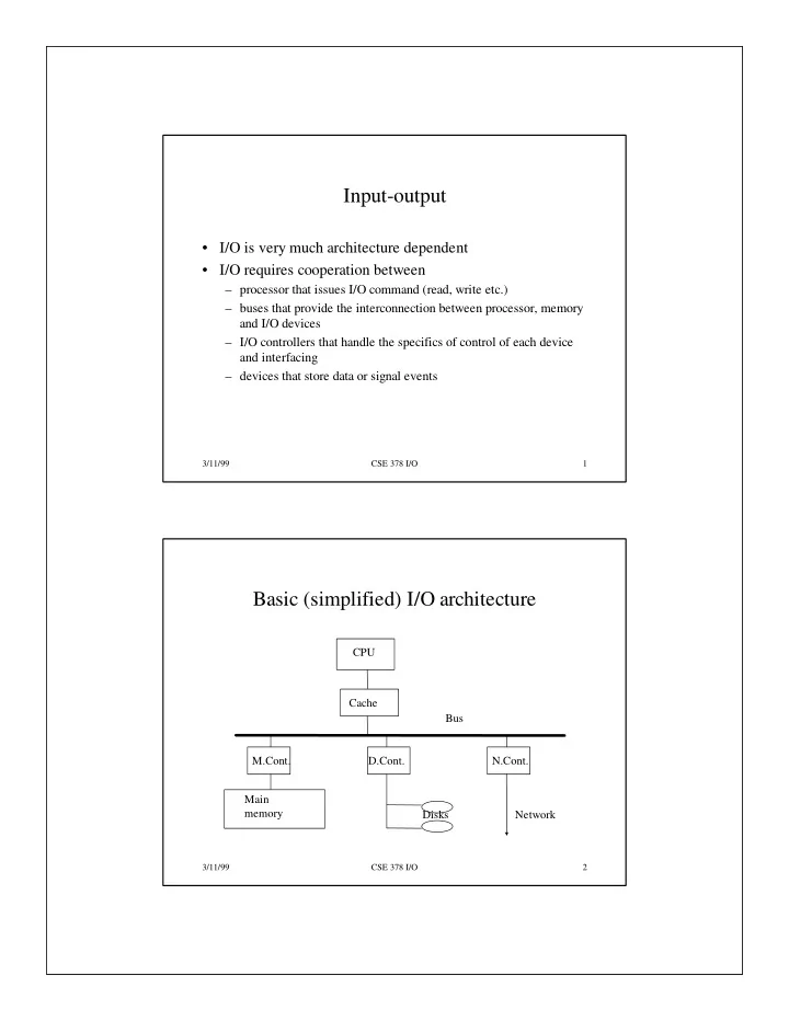
– processor that issues I/O command (read, write etc.) – buses that provide the interconnection between processor, memory and I/O devices – I/O controllers that handle the specifics of control of each device and interfacing – devices that store data or signal events

3/11/99 CSE 378 I/O 2

Basic (simplified) I/O architecture

CPU Cache M.Cont. D.Cont. N.Cont. Main memory Disks Network Bus

slide-2
SLIDE 2

3/11/99 CSE 378 I/O 3

Types of I/O devices

  • Input devices

– keyboard, mouse

  • Output devices

– screen, line printer

  • Devices for both input and output

– disks, connection to networks

3/11/99 CSE 378 I/O 4

An important I/O device: the disk

track sector Disk surface Read-write heads platters Cylinder

slide-3
SLIDE 3

3/11/99 CSE 378 I/O 5

Secondary memory (disks)

  • Physical characteristics

– Platters (1 to 20) with diameters from 1.3 to 8 inches (recording on both sides) – Tracks (500 to 2,500) – Cylinders (all the tracks in the same position in the platters) – Sectors (e.g., 128 sectors/track with gaps and info related to sectors between them; typical sector 512 bytes) – Current trend: constant bit density, i.e., more info on outer tracks – Example: Capacity = # platters * # tracks * # sectors * cap. sector 20 * 2,000 * 128 * 512 = approx. 2.5 GB

3/11/99 CSE 378 I/O 6

Disk access time

  • Arm(s) with a reading/writing head
  • Four components in an access:

– Seek time (to move the arm on the right cylinder) From 0 (if arm already positioned) to a maximum of 15-20 ms. Not a linear

  • function. Smaller disks have smaller seek times

– Rotation time (on the average 1/2 rotation). At 3600 RPM, 8.3 ms. Current disks are 3600 or 5400 or even 7200 RPM – Transfer time depends on rotation time, amount to transfer (minimal size a sector), recording density, disk/memory

  • connection. Today, transfer time occurs at 2 to 8 MB/second

– Disk controller time. Overhead to perform an access (of the order

  • f 1 ms)
slide-4
SLIDE 4

3/11/99 CSE 378 I/O 7

Improvements in disks

  • Capacity (via density). Same growth rate as DRAMs
  • Price decrease has followed (today $100/GB, maybe less)
  • Access times have not changed much

– Higher density -> smaller drives -> smaller seek time – RPM has increased slightly 3600 to 5400 and even 7200 – Transfer time about the same

  • CPU speed - DRAM access is one “memory wall”
  • DRAM access time - Disk access time is a “memory gap”

– Technologies to fill the gap have not succeeded (currently the most promising is more DRAM backed up by batteries)

3/11/99 CSE 378 I/O 8

Connecting CPU, Memory and I/O

CPU Cache CPU-Memory bus I/O bus

Bus adapter

Main memory I/O contr. I/O contr. I/O contr. disk Graphics Network

slide-5
SLIDE 5

3/11/99 CSE 378 I/O 9

Buses

  • Simplest interconnect

– Low cost: set of shared wires – Easy to add devices (although variety of devices might make the design more complex or less efficient -- longer bus and more load; hence the distinction between I/O buses and CPU/memory buses) – But single shared resource so can get saturated (both physically because of electrical load, and performance-wise because of contention to access it )

  • Key parameters:

– Width (number of lines:data, addresses, control) – Speed (limited by length and load)

3/11/99 CSE 378 I/O 10

Memory and I/O buses

  • CPU/memory bus: tailored to the particular CPU

– Fast (separate address and data lines) – Often short and hence synchronous (governed by a clock) – Wide (64-128 and even 256 bits) ) – Expensive

  • I/O bus: follows some standard so many types of devices

can be hooked on to it

– Asynchronous (hand-shaking protocol) – Narrower

slide-6
SLIDE 6

3/11/99 CSE 378 I/O 11

Bus transactions

  • Consists of arbitration and commands

– Arbitration: who is getting control of the bus – Commands: type of transaction (read, write, ack, etc…)

  • Read, Write, Atomic Read-Modify-Write (atomic swap)

– Read: send address and data is returned – Write: send address and data – Read-Modify-write : keep bus during the whole transaction .Used for synchronization between processes

3/11/99 CSE 378 I/O 12

Bus arbitration

  • Arbitration: who gets the bus if several requests at the

same time

– Only one master: centralized arbitration – Multiple masters (most common case): centralized arbitration (FIFO, daisy-chain, round-robin, combination of those) vs. decentralized arbitration (each device knows its own priority)

  • Communication protocol between master and slave

– Synchronous (for short buses - no clock skew - i.e. CPU/memory) – Asynchronous (hand-shaking finite-state machine; easier to accommodate many devices)

slide-7
SLIDE 7

3/11/99 CSE 378 I/O 13

Hand-shaking protocol

  • Example : Master (CPU) requests data from Slave (Mem)
  • 1. Master transmits a read request (control lines) and address

(address/data lines)

  • 2. Slave recognizes the request. Grabs the address and raises the Ack

control line.

  • 3. Master sees the Ack line high. Releases the request and data lines
  • 4. Slave sees the Read request low. Releases the Ack line
  • 5. Slave is ready to transmit data. Places data on data lines and raises

Data ready (control line)

  • 6. Master sees Data ready high. Grabs data and raises Ack
  • 7. Slave sees Ack high. Releases data line and Data Ready
  • 8. Master sees Data Ready low. Releases Ack. Transaction is finished

3/11/99 CSE 378 I/O 14

Split-transaction buses

  • Split a read transaction into

– Send address (CPU is master) – Send data (Memory is master) – In between these two transactions (memory access time) the bus is freed – Requires “tagging” the transaction

  • Can even have more concurrency by having different

transactions using the data and address lines concurrently

  • Useful for multiprocessor systems and for I/O
slide-8
SLIDE 8

3/11/99 CSE 378 I/O 15

I/O Hardware-software interface

  • I/O is best left to the O.S. (for protection and scheduling in

particular)

  • O.S. provides routines that handles devices (or controllers)
  • But since O.S. is a program, there must be instructions to

generate I/O commands

  • CPU must be able to:

– tell a device what it wants done (e.g., read, write, etc.) – start the operation (or tell the device controller to start it) – find out when the operation is completed (with or without error)

  • No unique way to do all this. Depends on ISA and I/O

architecture

3/11/99 CSE 378 I/O 16

I/O operations

  • Specific I/O instructions

– I/O instruction specifies both the device number and a command (or an address where the I/O device can find a series of commands) – Example: Intel x86 (IN and OUT between EAX register and an I/O port whose address is either an immediate or in the DX register)

  • Memory-mapped I/O

– Portions of address space devoted to I/O devices (read/write to these addresses transfer dataor are used to control I/O devices) – Memory ignores these addresses

  • In both cases, only the O.S. can execute I/O operations or

read/write data to memory-mapped locations

slide-9
SLIDE 9

3/11/99 CSE 378 I/O 17

I/O termination

  • Two techniques to know when an I/O operation terminates

– Polling – Interrupts

  • Polling

– CPU repeatedly checks whether a device has completed – Used for “slow” devices such as the mouse (30 times a second)

  • Interrupts

– When the I/O completes it generates an (I/O) interrupt

3/11/99 CSE 378 I/O 18

I/O interrupts

  • An interrupt is like an exception

– Exception created by the program (page fault, divide by zero etc.) – Interrupts occur as a consequence of external stimuli (I/O, power failure etc.)

  • Presence of an interrupt checked on every cycle
  • Upon an interrupt, O.S. takes over (context-switch)
  • Two basic schemes to handle the interrupt

– Vectored interrupts: the O.S. is told (by the hardware) where to handle the interrupt – Use of a cause register. The O.S. has to examine the contents of that register to transfer to the appropriate handler

slide-10
SLIDE 10

3/11/99 CSE 378 I/O 19

Data transfer to/from I/O device

  • Can be done either by

– Using the CPU to transfer data from (to) the device to (from memory.

  • Can be done either via polling (programmed I/O operation) or

interrupt

  • Slow operation

– Using DMA (direct-memory address)

3/11/99 CSE 378 I/O 20

DMA

  • Having long blocks of I/O go through the processor via

load-store is totally inefficient

  • DMA (direct memory address) controller:

– specialized processor for transfer of blocks between memory and I/O devices w/o intervention from CPU (except at beg. and end) – Has registers set up by CPU for beginning memory address and count – DMA device interrupts CPU at end of transfer – DMA device is a master for the bus – More complex DMA devices become I/O processors or channels controllers (with their own stored programs)

slide-11
SLIDE 11

3/11/99 CSE 378 I/O 21

DMA and virtual memory

  • What if the block to transfer is greater than 1 page

– Address translation registers within the DMA device

  • What if the O.S. replaces a page where transfer is taking place

– Pages are “pinned” (locked) during transfer

3/11/99 CSE 378 I/O 22

I/O and caches

  • Recall previous discussion

– Write-back caches:

  • on output, the O.S. flushes the cache before the page is written out
  • on input, blocks in the cache are invalidated

– Write-through caches

  • on output, no problem since cache and memory are consistent
  • on input, as in write-back
  • Another possibility

– Have the I/O go through the cache – Problem with performance (unused blocks in cache, interference with CPU)

slide-12
SLIDE 12

3/11/99 CSE 378 I/O 23

Disk arrays

  • Reliability: is anything broken?
  • Availability: is the system still usable?
  • Availability can be improved by adding more hardware

(e.g.,ECC, disk arrays) that provides some redundancy

  • In the case of I/O, simplest redundant system is mirroring:

write each data on two disks.

– Cost: double the amount of hardware – Performance: no increase (in fact might be worse for writes since has to wait for the longest of the two to complete)

3/11/99 CSE 378 I/O 24

RAIDs

  • Concept of striping: data written consecutively on N disks
  • Performance wise: no improvement in latency but

improvement in throughput (parallelism)

  • But now probability of failure is greater
  • So add disks (redundant arrays of inexpensive disks)

– Mirroring = RAID1 – RAID 5: interleave the parity sectors on the disks