Input/Output Introduction I/O requires cooperation between - - PowerPoint PPT Presentation

input output introduction
SMART_READER_LITE
LIVE PREVIEW

Input/Output Introduction I/O requires cooperation between - - PowerPoint PPT Presentation

Input/Output Introduction I/O requires cooperation between processor, memory, and devices: Processor issues I/O command Buses provide the interconnection between processor, memory, and the I/O devices Devices provide data (stored


slide-1
SLIDE 1

270 CSE378 WINTER, 2001

Input/Output

271 CSE378 WINTER, 2001

Introduction

  • I/O requires cooperation between processor, memory, and

devices:

  • Processor issues I/O command
  • Buses provide the interconnection between processor, memory,

and the I/O devices

  • Devices provide data (stored or input dynamically)
  • Evaluating I/O systems. Throughput:
  • Data rate - bytes/second
  • I/O rate - operations/second
  • Latency: (response time)
  • What are example applications where response time is

important? Throughput?

272 CSE378 WINTER, 2001
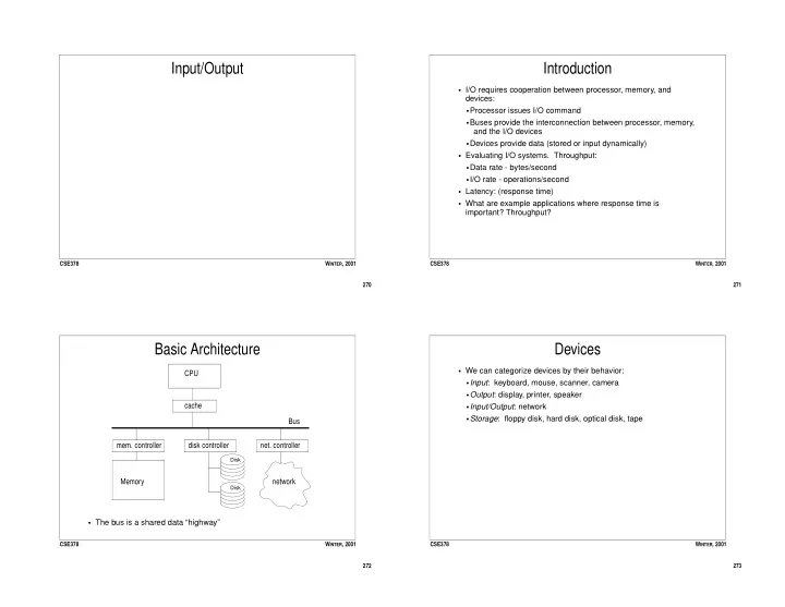
Basic Architecture

  • The bus is a shared data “highway”

Bus CPU cache Memory

  • mem. controller

disk controller

  • net. controller

Disk Disk

network

273 CSE378 WINTER, 2001

Devices

  • We can categorize devices by their behavior:
  • Input: keyboard, mouse, scanner, camera
  • Output: display, printer, speaker
  • Input/Output: network
  • Storage: floppy disk, hard disk, optical disk, tape
slide-2
SLIDE 2

274 CSE378 WINTER, 2001

An Important Device: Magnetic Disk

Platters Read/Write head A cylinder is the set of tracks at the same position

  • n all of the platters.

Sector Track 275 CSE378 WINTER, 2001

Disk Components

  • A disk consists of one or more platters (2 to 20). The platters

rotate (up to 10000 rpm).

  • Each platter (diameter 1 - 10 inches) is composed of concentric

tracks (10,000s tracks/surface; 2 surfaces/platter)

  • Tracks are divided into sectors (32 to 128 sectors/track). The

sector is the smallest unit that can be read/written.

  • A cyclinder is the set of tracks under the read/write heads.
  • Typical numbers for a 36 GB disk in 2001:
  • 6 x 3.5 inch diameter platters, 16383 cylinders, 6 tracks/cylinder,

63 sectors/track, 512 bytes/sector, 10000 rpm,

276 CSE378 WINTER, 2001

Disk Operation and Timing

  • To perform a transfer (read or write):
  • Seek: place the heads over the right track.
  • Rotate: wait until the right sector is under the head.
  • Transfer: transfer the number of sectors dictated by the operation
  • Total time = seek time + rotation time + transfer time
  • Typical times:
  • Average seek time = 5-10 ms (better with smaller disks)
  • Average rotational latency = (1/2 disk rotation). At 10000 rpm,

this is about 3 ms.

  • Transfer rate = ~10 MB/s (sustained)
  • Also remember to add the time needed by the OS and disk

controller to initiate operation (on the order of 1 ms).

277 CSE378 WINTER, 2001

Disk Scheduling

  • Seek time can be optimized by scheduling multiple requests so

that arms move as little as possible.

  • Different schemes:
  • FIFO - no optimization: service requests in order received
  • Shortest seek first - favors tracks in the middle of the disk and

can lead to starvation

  • Elevator - good average
slide-3
SLIDE 3

278 CSE378 WINTER, 2001

Buses

  • Each bus defines a protocol for communication between

connected devices.

  • Types of buses:
  • Processor-memory (generally specific to processor)
  • I/O bus (standardized so I/O devices from different

manufacturers can communicate)

  • Backplane buses (allow processor, memory, I/O devices to exist
  • n a single bus)
  • Bus protocols can be synchronous (goverened by clock). This is
  • nly good for short buses and when answers are expected in

short number of cycles (e.g. processor-memory). They are typically quite fast.

  • Or the protocol can be asynchronous, depending on
  • handshaking. Used in I/O buses.

279 CSE378 WINTER, 2001

Bus components

  • A bus is a set of lines (wires):
  • Address lines
  • Data lines
  • Control lines
  • Address and data lines can be multiplexed if space is precious,

and time affordable.

  • A transaction consists of arbitration (who gets control of the bus)

and commands (read request, acknowledgements, transfer of data)

280 CSE378 WINTER, 2001

Arbitration

  • Several devices may want to use the bus at the same time.
  • Requesting devices are called masters.
  • The processor is always a master.
  • If there is more than one master, we need arbitration:
  • Arbitration can take place by:
  • priority: each device has predetermined priority.
  • round-robin: each device in turn has highest priority.
  • Arbitration can be:
  • centralized: a central entity decides who wins control of the bus.
  • decentralized: devices decide in parallel who wins control (either

through self-reflection or collision detection).

281 CSE378 WINTER, 2001

Bus Summary & Examples

  • Design Parameters:
  • Width: wider, non-multiplexed lines is faster and $
  • Transfer size: multiple words per request requires less overhead,

but single word is cheaper.

  • Masters: multiple is more flexible, higher performance, requires

arbitration

  • Clocking: synchronous is faster, but works only on short bussesI/

O Bus:

  • Examples:
  • PCI bus (Backplane): 32-64 bits wide, synchronous, 33-66 MHz,

peak bandwidth = 110 MB/s, multiple masters

  • Intel (System): 64 bits wide, synchronous, 133MHz, peak

bandwidth = 1.06 GB/second

  • AMD (System): 64 bits wide, synchronous, 200-400MHz, peak

bandwidth = 1.6 GB/second

slide-4
SLIDE 4

282 CSE378 WINTER, 2001

Hardware/Software Interface

  • OS usually protects users from having to deal with devices

directly.

  • The CPU (under OS control) must be able to:
  • Tell a device what to do (eg read)
  • Start the operation on the device
  • Find out if the operation has completed
  • Find out if there was an error
  • There is no universal way to do this: depends on the ISA and the

I/O architecture

283 CSE378 WINTER, 2001

CPU - Device Interaction

  • Two basic ways for the CPU to control devices:
  • Specific I/O instructions: An I/O instruction specifies both the

device number and a command

  • Memory mapped I/O: Device controllers appear to be (reserved)

memory addresses. When data is written to that address, it is ignored by real memory, but interpreted by the device controller as a command.

  • There are two schemes for knowing when a device is finished:
  • Polling: the CPU repeatedly checks whether a device has
  • completed. This is time consuming if the device needs to be

polled often.

  • Interrupts: the CPU initiates the operation (on behalf of some

process) and then context switches to another process. When the operation completes, the IO device interrupts the CPU.

284 CSE378 WINTER, 2001

I/O Device - Memory Transfers

  • Suppose we’re moving data from the HD to memory.
  • Polling is clearly a CPU intensive solution.
  • Interrupts are better, but can still consume many CPU cycles (b/

c the CPU gets interrupted after every block is transferred).

  • A better approach is Direct Memory Access (DMA)
  • Need a DMA device (controller) to take care of effecting the

transfer.

  • To perform a transfer:
  • CPU sets up transfer by communicating with the controller
  • The controller performs the transfer while the CPU does other

work.

  • When finished, the controller interrupts the CPU.

285 CSE378 WINTER, 2001

Food For Thought

  • CPU performance has been improving at a rate of 60% per year.
  • DRAM access time has been improving at a rate of 10% per year.
  • How do the various techniques/concepts we have studied either

impact or address this growing bottleneck?

  • Caching
  • Pipelining
  • Superscalar processing
  • Address translation/virtual memory
  • Bus technology