Huffman Coding Variable Rate Codes Example: David A. Huffman - - PowerPoint PPT Presentation

huffman coding variable rate codes
SMART_READER_LITE
LIVE PREVIEW

Huffman Coding Variable Rate Codes Example: David A. Huffman - - PowerPoint PPT Presentation

Huffman Coding Variable Rate Codes Example: David A. Huffman (1951) Huffman coding uses frequencies of symbols in a string to build a variable rate prefix code 1) A 00 ; B 01 ; C 10 ; D 11 ; Each symbol is mapped


slide-1
SLIDE 1

Huffman Coding

  • David A. Huffman (1951)
  • Huffman coding uses frequencies of symbols in a string to build a variable rate prefix code
  • Each symbol is mapped to a binary string
  • More frequent symbols have shorter codes
  • No code is a prefix of another

27/02/2011 Applied Algorithmics - week7 1

  • No code is a prefix of another
  • Example:

A 0 B 100 C 101 D 11 D C B A 1 1 1

Variable Rate Codes

Example:

1) A → 00; B → 01; C → 10; D → 11; 2) A → 0; B → 100; C → 101; D → 11;

27/02/2011 Applied Algorithmics - week7 2

Two different encodings of AABDDCAA

0000011111100000

(16 bits)

00100111110100

(14 bits)

Cost of Huffman Trees

Let A={a1, a2, .., am} be the alphabet in which each

symbol ai has probability pi

We can define the cost of the Huffman tree HT as m

27/02/2011 Applied Algorithmics - week7 3
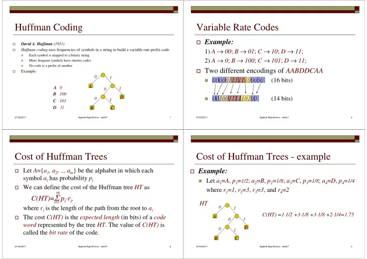
C(HT)=Σ pi·ri,

where ri is the length of the path from the root to ai

The cost C(HT) is the expected length (in bits) of a code

word represented by the tree HT. The value of C(HT) is called the bit rate of the code.

i=1

Cost of Huffman Trees - example

Example:

Let a1=A, p1=1/2; a2=B, p2=1/8; a3=C, p3=1/8; a4=D, p4=1/4

where r1=1, r2=3, r3=3, and r4=2

27/02/2011 Applied Algorithmics - week7 4

D C B A 1 1 1

HT

C(HT) =1·1/2 +3·1/8 +3·1/8 +2·1/4=1.75

slide-2
SLIDE 2

Huffman Tree Property

Input: Given probabilities p1, p2, .., pm for symbols a1, a2,

.., am from alphabet A

Output: A tree that minimizes the average number of bits

(bit rate) to code a symbol from A

27/02/2011 Applied Algorithmics - week7 5

(bit rate) to code a symbol from A

I.e., the goal is to minimize function:

C(HT)=Σ pi·ri, where ri is the length of the path from the root to leaf ai. This is called a Huffman tree or Huffman code for alphabet A

Huffman Tree Property

Input: Given probabilities p1, p2, .., pm for symbols a1, a2,

.., am from alphabet A

Output: A tree that minimizes the average number of bits

(bit rate) to code a symbol from A

27/02/2011 Applied Algorithmics - week7 6

(bit rate) to code a symbol from A

I.e., the goal is to minimize function:

C(HT)=Σ pi·ri, where ri is the length of the path from the root to leaf ai. This is called a Huffman tree or Huffman code for alphabet A

Construction of Huffman Trees

Form a (tree) node for each symbol ai with weight pi Insert all nodes to a priority queue PQ (e.g., a heap)

  • rdered by nodes probabilities

while (the priority queue has more than two nodes)

27/02/2011 Applied Algorithmics - week7 7

while (the priority queue has more than two nodes)

  • min1 ← remove-min(PQ); min2 ← remove-min(PQ);
  • create a new (tree) node T;
  • T.weight ← min1.weight + min2.weight;
  • T.left ← min1; T.right ← min2;
  • insert(PQ, T)

return (last node in PQ)

Construction of Huffman Trees

P(A)= 0.4, P(B)= 0.1, P(C)= 0.3, P(D)= 0.1, P(E)= 0.1

A

0.4

B D E

0.1 0.1 0.1

C

0.3

27/02/2011 Applied Algorithmics - week7 8

A B D E A B C D E C

0.4 0.1 0.3 0.2

slide-3
SLIDE 3

Construction of Huffman Trees

B D E

0.1 0.2

1

A C

0.4 0.3

27/02/2011 Applied Algorithmics - week7 9

A C

0.4 0.3

1

D E

1

B

0.3

Construction of Huffman Trees

A C

0.4 0.3

1

B

0.3

A

0.4

C

0.6

1

27/02/2011 Applied Algorithmics - week7 10

D E

1

B

1

D E

1

B C

Construction of Huffman Trees

A

0.4 0.6

1 1

A

27/02/2011 Applied Algorithmics - week7 11

1

D E

1

B C

1

D E

1

B C

1

A

Construction of Huffman Trees

1 1

A A = 0 B = 100

27/02/2011 Applied Algorithmics - week7 12

1

D E

1

B C

1

C = 11 D = 1010 E = 1011

slide-4
SLIDE 4

Huffman Codes

Theorem: For any source S the Huffman code can

be computed efficiently in time O(n·log n) , where n is the size of the source S.

27/02/2011 Applied Algorithmics - week7 13

Proof: The time complexity of Huffman coding algorithm is dominated by the use of priority queues

One can also prove that Huffman coding creates the

most efficient set of prefix codes for a given text

It is also one of the most efficient entropy coder

Basics of Information Theory

The entropy of an information source (string) S built over

alphabet A={a1, a2, .., am}is defined as: H(S) = i pi·log2(1/pi) where pi is the probability that symbol ai in S will occur

27/02/2011 Applied Algorithmics - week7 14

where pi is the probability that symbol ai in S will occur

log2(1/pi) indicates the amount of information contained

in ai, i.e., the number of bits needed to code ai.

For example, in an image with uniform distribution of

gray-level intensity, i.e. all pi = 1/256, then the number of bits needed to encode each gray level is 8 bits. The entropy of this image is 8.

Huffman Code vs. Entropy

Entropy:

0.4 · log2(10/4) + 0.1 · log2(10) + 0.3 · log2(10/3) +

P(A)= 0.4, P(B)= 0.1, P(C)= 0.3, P(D)= 0.1, P(E)= 0.1

27/02/2011 Applied Algorithmics - week7 15

0.4 · log2(10/4) + 0.1 · log2(10) + 0.3 · log2(10/3) +

0.1 · log2(10) + 0.1 · log2(10) = 2.05 bits per symbol

Huffman Code:

0.4 · 1 + 0.1 · 3 + 0.3 · 2 + 0.1 · 4 + 0.1 · 4 = 2.10 Not bad, not bad at all.

Error detection and correction

Hamming codes:

  • codewords in Hamming (error detecting and error correcting)

codes consist of m data bits and r redundant bits.

  • Hamming distance between two strings represents the number

27/02/2011 Applied Algorithmics - week8 16

  • Hamming distance between two strings represents the number
  • f bit positions on which two bit patterns differ (similar to

pattern matching k mismatches).

  • Hamming distance of the code is determined by the two

codewords whose Hamming distance is the smallest.

  • error detection involves determining if codewords in the

received message match closely enough legal codewords.

slide-5
SLIDE 5

Error detection and correction

x x

  • A code with poor distance properties

A code with good distance properties (a) (b)

27/02/2011 Applied Algorithmics - week8 17

x = codewords

  • = non-codewords

x x x x x x

  • x

x x x x x x

  • code distance

Error detection and correction

To detect properly d single bit errors, one needs to apply a

d+1 code distance.

To correct properly d single bit errors, one needs to apply

a 2d+1 code distance.

27/02/2011 Applied Algorithmics - week8 18

a 2d+1 code distance.

In general, the price for redundant bits is too expensive (!!)

to do error correction for all network messages

Thus safety and integrity of network communication is

based on error detecting codes and extra transmissions in case any errors were detected

Recalculate Information bits Received information bits

Error-Detection System using Check Bits

27/02/2011 Applied Algorithmics - week8 19

Calculate check bits Channel check bits Compare Check bits Information accepted if check bits match Received check bits

Cyclic Redundancy Checking (CRC)

cyclic redundancy check (CRC) is a popular technique for detecting data transmission errors. Transmitted messages are divided into predetermined lengths

27/02/2011 Applied Algorithmics - week8 20

messages are divided into predetermined lengths that are divided by a fixed divisor. According to the calculation, the remainder number is appended

  • nto and sent with the message. When the message

is received, the computer recalculates the remainder and compares it to the transmitted remainder. If the numbers do not match, an error is detected.

slide-6
SLIDE 6

Error detection -- via parity of subsets of bits

27/02/2011 Applied Algorithmics - week8 21

  • Detection via parity of subsets of bits

P2P1P0 Add 3 parity bits.

? ? ?

Each parity bit computed on a subset of bits

Consider 4 bit words.

1 1

D3D2D1D0

27/02/2011 Applied Algorithmics - week8 22

Each parity bit computed on a subset of bits

P0= D3 xor D1 xor D0 = 0 xor 1 xor 0 = 1 P1 = D3 xor D2 xor D0 = 0 xor 1 xor 0 = 1 P2= D3 xor D2 xor D1 = 0 xor 1 xor 1 = 0 D3D2D1P2D0P1P0

Use this word bit arrangement

1 1 1 1

Check bits occupy power of 2 slots!

Detection via parity of subsets of bits - no error occurred

And computes: First, we send: Later, someone gets:

No error occurred. But how do we know that? D3D2D1P2D0P1P0

1 1 1 1

D3D2D1P2D0P1P0

1 1 1 1

27/02/2011 Applied Algorithmics - week8 23

And computes: If all B2,B1,B0 = 0 there are no errors! These equations come from how we computed:

B0= P0 xor D3 xor D1 xor D0 = 1 xor 0 xor 1 xor 0 = 0 B1= P1 xor D3 xor D2 xor D0 = 1 xor 0 xor 1 xor 0 = 0 B2= P2 xor D3 xor D2 xor D1 = 0 xor 0 xor 1 xor 1 = 0 P0= D3 xor D1 xor D0 = 0 xor 1 xor 0 = 1 P1 = D3 xor D2 xor D0 = 0 xor 1 xor 0 = 1 P2= D3 xor D2 xor D1 = 0 xor 1 xor 1 = 0

Detection via parity of subsets of bits - single bit is twisted

First, we send: Later, someone gets:

What if a cosmic ray hit D1? How would we know that?

And computes:

D3D2D1P2D0P1P0

1 1 1 1

D3D2D1P2D0P1P0

1 1 1

27/02/2011 Applied Algorithmics - week8 24

And what does 101= 5 mean? The position of the flipped bit! To repair, just flip it back

We number the least significant bit with 1, not 0! 0 is reserved for “no errors”.

And computes:

B0= P0 xor D3 xor D1 xor D0 = 1 xor 0 xor 0 xor 0 = 1 B1= P1 xor D3 xor D2 xor D0 = 1 xor 0 xor 1 xor 0 = 0 B2= P2 xor D3 xor D2 xor D1 = 0 xor 0 xor 1 xor 0 = 1 B2B1B₀ = 101 = 5

1 1 1 7 5 6 3 4 2 1

D3D2D1P2D0P1P0

slide-7
SLIDE 7

For any 4 bit word we add 3 parity bits

Detection via parity of subsets of bits - magic trick revealed

P2P1P0

? ? ? 1 1

D3D2D1D0

27/02/2011 Applied Algorithmics - week8 25

Observation: The parity bits need to encode “no error” scenario, plus a number for each bit (both data and parity bits) For p parity bits and d data bits: d + p + 1 2p Question: Why do we arrange bits?

Start by numbering, For any 4 bit word we add 3 parity bits P2P1P0 D3D2D1D0

Detection via parity of subsets of bits - magic trick revealed

27/02/2011 Applied Algorithmics - week8 26

1 to 7. With this order, an odd parity means an error in 1,3,5, or 7. So, P0 is the right parity bit to use: D3D2 D0P1P₀

₀ ₀ ₀

An odd parity means a mistake must be in 2, 3, 6, or 7 -- the four numbers possible if P1 = 1! D3D2D1P2₁

₁ ₁ ₁P₀ ₀ ₀ ₀

etc ... each bit narrows down the suspect bits, until it is certain. D3D2D1P2D0P1P0

7 5 6 3 4 2 1

D3 D1 D0 P0 P₀ = D3 xor D1 xor D0 P1 = D3 xor D2 xor D0 P2 = D3 xor D2 xor D1

7 bits can code 128 numbers, but only 16

D₃ ₃ ₃ ₃D₂ ₂ ₂ ₂D₁ ₁ ₁ ₁P₂ ₂ ₂ ₂D₀ ₀ ₀ ₀P₁ ₁ ₁ ₁P₀ ₀ ₀ ₀

Detection via parity of subsets of bits - magic trick revealed

For any 4 bit word we add 3 parity bits P2P1P0 D3D2D1D0

  • 27/02/2011

Applied Algorithmics - week8 27

It takes 3 bit flips to move from one legal number to another (for all 16 numbers) If only one bit flips, we can always figure out the “closest” legal number, and correct the number. 7 bits can code 128 numbers, but only 16

  • f these numbers are legal.