High Power, Low Cost SOFC Stacks For Robust And Reliable - - PowerPoint PPT Presentation

high power low cost sofc stacks for robust and reliable
SMART_READER_LITE
LIVE PREVIEW

High Power, Low Cost SOFC Stacks For Robust And Reliable - - PowerPoint PPT Presentation

High Power, Low Cost SOFC Stacks For Robust And Reliable Distributed Genera?on Redox Cube 25 kW, natural gas, Award No. DE-FE0026189 sta6onary


slide-1
SLIDE 1

High ¡Power, ¡Low ¡Cost ¡SOFC ¡ Stacks ¡For ¡Robust ¡And ¡Reliable ¡ Distributed ¡Genera?on ¡

PI: ¡Bryan ¡Blackburn, ¡Ph.D. ¡ Redox ¡Power ¡Systems, ¡LLC ¡

Project ¡Kickoff ¡12/02/2015 ¡
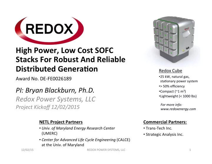
Redox ¡Cube ¡

  • 25 ¡kW, ¡natural ¡gas, ¡

sta6onary ¡power ¡system ¡

  • > ¡50% ¡efficiency ¡
  • Compact ¡(~1 ¡m3) ¡
  • Lightweight ¡(< ¡1000 ¡lbs) ¡

¡ NETL ¡Project ¡Partners ¡

  • Univ. ¡of ¡Maryland ¡Energy ¡Research ¡Center ¡ ¡

(UMERC) ¡ ¡

  • Center ¡for ¡Advanced ¡Life ¡Cycle ¡Engineering ¡(CALCE) ¡

at ¡the ¡Univ. ¡of ¡Maryland ¡

Award ¡No. ¡DE-­‑FE0026189 ¡

Commercial ¡Partners: ¡

  • Trans-­‑Tech ¡Inc. ¡
  • Strategic ¡Analysis ¡Inc. ¡

12/02/15 ¡ REDOX ¡POWER ¡SYSTEMS, ¡LLC ¡ 1 ¡

For ¡more ¡info: ¡ ¡ www.redoxenergy.com ¡

slide-2
SLIDE 2
  • Redox ¡Power ¡Systems ¡founded ¡in ¡2012, ¡ ¡

located ¡in ¡College ¡Park, ¡MD ¡ ¡

  • Over ¡25 ¡years ¡of ¡Solid ¡Oxide ¡Fuel ¡Cell ¡(SOFC) ¡ ¡ ¡ ¡ ¡ ¡ ¡ ¡ ¡ ¡ ¡ ¡ ¡ ¡ ¡ ¡ ¡ ¡

development ¡to ¡achieve: ¡

– 10x ¡higher ¡power ¡density ¡than ¡compe6ng ¡SOFCs ¡ ¡ – At ¡100s ¡of ¡degrees ¡lower ¡opera6ng ¡temperature ¡ – Using ¡natural ¡gas ¡fuel ¡ – To ¡result ¡in ¡a ¡more ¡compact ¡and ¡lower ¡cost ¡system ¡ ¡ ¡ ¡ ¡ ¡ ¡ ¡ ¡ ¡ ¡ ¡ ¡ ¡ ¡ ¡ ¡with ¡improved ¡load ¡following ¡capabili6es ¡ – Using ¡a ¡proprietary ¡bilayer ¡cell ¡structure ¡

  • Private ¡+ ¡gov’t ¡funding: ¡DoE ¡(ARPAE, ¡EERE, ¡NETL) ¡& ¡DoD ¡
  • SOFC ¡cells ¡are ¡manufactured ¡with ¡our ¡ISO ¡9001 ¡partner ¡

Trans-­‑Tech ¡Inc, ¡a ¡division ¡of ¡Skyworks ¡Solu6ons ¡

12/02/15 ¡ REDOX ¡POWER ¡SYSTEMS, ¡LLC ¡ 2 ¡

Introduction to Redox

slide-3
SLIDE 3

Redox Product Manufacturing Overview

25 ¡kWe ¡Cube ¡System ¡

Common ¡high ¡volume ¡appliance ¡ and ¡electronics ¡manufacturing, ¡ COTs ¡components ¡ Specialized ¡manufacturing, ¡ custom ¡components ¡ Raw ¡ Oxide ¡ Powders ¡ ~100W ¡ Bilayer ¡ SOFC ¡Cells ¡ 1 ¡to ¡10 ¡kWe ¡ SOFC ¡ Stacks ¡ Balance ¡Of ¡ Plant ¡

12/02/15 ¡ REDOX ¡POWER ¡SYSTEMS, ¡LLC ¡ 3 ¡

slide-4
SLIDE 4
  • UMERC ¡(under ¡direc6on ¡of ¡Prof. ¡Eric ¡Wachsman) ¡

– mul6disciplinary ¡ini6a6ve ¡dedicated ¡to ¡advancing ¡the ¡fron6ers ¡of ¡energy ¡science ¡and ¡ technology, ¡with ¡a ¡special ¡focus ¡on ¡forward-­‑looking ¡approaches ¡for ¡alterna6ve ¡energy ¡ genera6on ¡and ¡storage ¡ – heavily ¡involved ¡in ¡NETL ¡SOFC ¡degrada6on ¡inves6ga6ons ¡for ¡more ¡than ¡a ¡decade ¡ – developed ¡unique ¡techniques ¡for ¡inves6ga6ng ¡degrada6on ¡of ¡cathode ¡materials ¡using ¡ isotope ¡exchange ¡ – pioneered ¡the ¡use ¡of ¡FIB-­‑SEM ¡reconstruc6on ¡to ¡to ¡quan6fy ¡porous ¡cathode ¡microstructure ¡at ¡ the ¡sub-­‑micron ¡level ¡and ¡ul6mately ¡to ¡develop ¡higher ¡performance ¡cathodes ¡

  • CALCE ¡(under ¡direc6on ¡of ¡Prof. ¡Michael ¡Pecht) ¡

– founder ¡and ¡driving ¡force ¡behind ¡the ¡development ¡and ¡implementa6on ¡of ¡physics-­‑of-­‑failure ¡ (PoF) ¡approaches ¡to ¡reliability ¡ – world ¡leader ¡in ¡accelerated ¡tes6ng, ¡electronic ¡parts ¡selec6on ¡and ¡management, ¡and ¡supply-­‑ chain ¡management ¡ – first ¡academic ¡research ¡facility ¡in ¡the ¡world ¡to ¡be ¡ISO ¡9001 ¡cer6fied ¡ – funded ¡by ¡over ¡150 ¡of ¡the ¡worlds ¡leading ¡electronics ¡companies ¡at ¡more ¡than ¡US$6M/year ¡ – Experience ¡developing ¡techniques ¡for ¡extending ¡the ¡life6me ¡of ¡electrochemical ¡devices, ¡such ¡ as ¡lithium ¡ion ¡baheries, ¡under ¡real ¡world ¡opera6ng ¡condi6ons ¡

Introduction to Partner Organizations

12/02/15 ¡ REDOX ¡POWER ¡SYSTEMS, ¡LLC ¡ 4 ¡

slide-5
SLIDE 5
  • Purpose: ¡To ¡further ¡develop ¡high ¡power ¡density, ¡low ¡cost ¡SOFC ¡

stacks ¡for ¡robust ¡and ¡reliable ¡distributed ¡genera6on. ¡

  • The ¡objec6ve ¡of ¡the ¡overall ¡project ¡is ¡to ¡improve ¡performance/

durability ¡of ¡Redox ¡stacks ¡while ¡reducing ¡costs ¡through: ¡ ¡

– the ¡scale-­‑up ¡of ¡current ¡stack ¡module ¡designs ¡to ¡5-­‑10 ¡kW ¡ ¡ – the ¡determina6on ¡of ¡cell ¡and ¡stack ¡degrada6on ¡mechanisms ¡between ¡ 500-­‑650°C ¡through ¡accelerated ¡tes6ng ¡and ¡subsequent ¡cell ¡and ¡stack ¡

  • p6miza6on ¡to ¡improve ¡long-­‑term ¡stability ¡

– the ¡development ¡and ¡tes6ng ¡of ¡a ¡robust ¡5-­‑10 ¡kW ¡stack ¡design ¡that ¡can ¡ support ¡electrical ¡load ¡and ¡thermal ¡cycling ¡requirements ¡ – detailed ¡cost ¡analysis ¡to ¡show ¡a ¡20% ¡manufacturing ¡cost ¡improvement ¡for ¡ the ¡stack ¡over ¡current ¡2020 ¡DOE ¡cost ¡targets ¡

5 ¡

NETL Project Objectives

REDOX ¡POWER ¡SYSTEMS, ¡LLC ¡ 12/02/15 ¡

slide-6
SLIDE 6

REDOX ¡POWER ¡SYSTEMS, ¡LLC ¡ 6 ¡

Approach Summary: IT-SOFC Stack

  • Increased Efficiency
  • Er stabilized Bi2O3 (ESB):

* 60X conductivity of YSZ @ 600°C * unstable at low PO2 (fuel conditions)

  • Gd doped CeO2 (GDC):

* > 5X conductivity of YSZ @ at 600°C * electronic leakage in fuel conditions, lowers efficiency

  • Solution: a bilayer of GDC (fuel side) and ESB, stops ceria electronic leakage & Bi2O3 decomposition
  • Goal: Optimize bilayer for best compromise between stability and performance in stack up to 10 kW ¡

12/02/15 ¡

slide-7
SLIDE 7
  • Optimized designs for 5-10 kW stacks and IT operation

– 500-650°C operating temperatures – Use proprietary Redox multi-physics bilayer model to optimize stack design for up to 10 kW – Support modeling with elevated temperature mechanical testing (stress concentrations and creep) – Improve assembly techniques (e.g., alignment and compression load)

  • 5-10 kW stack demo

– Bilayer cell performance maps for up to 10 kW stack, feed results back to model for design optimization – Long term testing > 1,000 hours – Fully instrumented test setup for evaluation of fuel utilization, degradation, and performance

REDOX ¡POWER ¡SYSTEMS, ¡LLC ¡ 7 ¡

Approach Summary: IT-SOFC Stack

12/02/15 ¡

  • The ¡Cell ¡

– Bilayer ¡electrolyte ¡+high ¡performance ¡cathode ¡yield ¡ultra ¡high ¡power ¡density ¡ ¡ ¡ ¡ ¡ ¡ ¡ (> ¡2 ¡W/cm2 ¡in ¡lab ¡tes6ng) ¡ – Lower ¡opera6ng ¡temperatures ¡(down ¡to ¡< ¡400 ¡°C, ¡or ¡700 ¡°F) ¡ – Current ¡anodes ¡can ¡run ¡on ¡wide ¡range ¡of ¡hydrocarbon ¡fuels ¡with ¡high ¡efficiency ¡ – New ¡ceramic ¡anodes ¡can ¡also ¡be ¡thermally ¡cycled ¡for ¡enhanced ¡load ¡following ¡

  • The ¡Stack ¡

– Lower ¡opera6ng ¡temperatures ¡= ¡lower ¡cost ¡metal ¡interconnects, ¡less ¡insula6on ¡ – Conven6onal ¡sealing ¡materials ¡like ¡those ¡used ¡in ¡automo6ve ¡industry ¡

slide-8
SLIDE 8
  • Large ¡format ¡cells ¡with ¡high ¡

power ¡have ¡been ¡scaled ¡in ¡ manufacturing ¡

– 10 ¡cm ¡by ¡10 ¡cm ¡cell ¡performance ¡ matches ¡buhon ¡cell ¡results ¡in ¡100% ¡slip ¡ condi6on ¡(21% ¡CH4, ¡39% ¡H2, ¡4.4% ¡CO) ¡

  • ¡1 ¡kW ¡stack ¡size ¡to ¡be ¡scaled ¡

to ¡5-­‑10 ¡kW ¡size ¡

– Single ¡stack, ¡or ¡ – Stack ¡module ¡(no ¡less ¡than ¡2.5 ¡kW ¡ each) ¡

REDOX ¡POWER ¡SYSTEMS, ¡LLC ¡ 8 ¡

650°C ¡

(single ¡GDC ¡electrolyte) ¡

High Power, Robust Stack

12/02/15 ¡

slide-9
SLIDE 9
  • Task ¡1: ¡Project ¡Management ¡and ¡Planning ¡

¡

  • Task ¡2: ¡Develop ¡High ¡Power, ¡Robust, ¡Low ¡Cost ¡

¡IT-­‑SOFC ¡ ¡Stacks ¡

  • Task ¡3: ¡Improve ¡Long-­‑Term ¡Stability ¡and ¡Reliability ¡of ¡High ¡

¡Power, ¡IT-­‑SOFC ¡Stacks ¡

  • Task ¡4: ¡Demonstrate ¡a ¡Robust ¡5-­‑10 ¡kW ¡Stack ¡or ¡Stack ¡

¡Module ¡for ¡Distributed ¡Genera6on ¡

  • Task ¡5: ¡Perform ¡a ¡Detailed ¡Cost ¡Analysis ¡of ¡High ¡Power, ¡IT-­‑

¡SOFC ¡Stacks ¡

12/02/15 ¡ REDOX ¡POWER ¡SYSTEMS, ¡LLC ¡ 9 ¡

Project Task Summary

slide-10
SLIDE 10
  • Custom ¡3D ¡computa6onal ¡model ¡takes ¡into ¡account ¡the ¡unique ¡thermochemical ¡and ¡physical ¡proper6es ¡of ¡the ¡

Redox ¡materials ¡as ¡derived ¡from ¡more ¡fundamental ¡materials ¡and ¡electrochemical ¡measurements ¡

  • Model ¡considers ¡impacts ¡of ¡leakage ¡current ¡(electron ¡current) ¡on ¡the ¡OCV ¡drops ¡from ¡theore6cal ¡Nernst ¡poten6al ¡

due ¡to ¡over-­‑poten6als ¡associated ¡with ¡the ¡electrolyte ¡and ¡electrodes ¡

  • Model ¡also ¡captures ¡the ¡kine6cs ¡of ¡electrochemical ¡and ¡heterogeneous ¡internal ¡reforming ¡reac6ons ¡in ¡the ¡anode ¡ ¡

!

Detailed ¡Single ¡ Channel ¡Model ¡

50% CH4 slip No CH4 slip H2

(b) (a) H2 (b) CH4 (C) CO

(a) ¡Mole ¡frac6on ¡of ¡H2 ¡for ¡0.7V ¡at ¡standard ¡fuel ¡u6liza6on ¡for ¡0% ¡CH4 ¡slip ¡at ¡600°C ¡inlet ¡temp. ¡ (b) ¡2D ¡current ¡distribu6on ¡for ¡3 ¡anode ¡fuel ¡feeds ¡opera6ng ¡at ¡0.7 ¡V ¡and ¡600°C ¡and ¡a ¡Uf ¡of ¡80% ¡ ¡

Bilayer ¡physics ¡captured ¡ Expandable ¡to ¡enQre ¡stack ¡

Multi-Physics Tool for Stack Scale-up

REDOX ¡POWER ¡SYSTEMS, ¡LLC ¡ 10 ¡ 12/02/15 ¡

Task ¡2 ¡

slide-11
SLIDE 11
  • Op6mize ¡stack ¡design ¡through ¡parametric ¡studies ¡

– cell ¡geometry/composi6on ¡and ¡interconnect ¡flow ¡field ¡ geometry) ¡to ¡minimize ¡pressure ¡drops, ¡improve ¡flow ¡ distribu6on, ¡and ¡minimize ¡thermal ¡gradients ¡under ¡ rapid ¡startup, ¡normal ¡opera6on, ¡and ¡load-­‑following ¡ condi6ons ¡ – Mechanical ¡degrada6on ¡through ¡thermal ¡gradients ¡ and ¡phenomena ¡such ¡as ¡creep ¡at ¡elevated ¡ temperatures ¡

  • Evaluate ¡cell/stack ¡performance ¡in ¡conjunc6on ¡

with ¡accelerated ¡tes6ng ¡and ¡lifecycle ¡tes6ng ¡to ¡ help ¡choose ¡final ¡opera6ng ¡condi6ons ¡for ¡tests ¡ and ¡to ¡help ¡analyze ¡results. ¡

12/02/15 ¡ REDOX ¡POWER ¡SYSTEMS, ¡LLC ¡ 11 ¡

Modeling Effort in NETL Project

Task ¡2 ¡

slide-12
SLIDE 12

12/02/15 ¡ REDOX ¡POWER ¡SYSTEMS, ¡LLC ¡ 12 ¡ Fuel ¡to ¡oxidant ¡measurement ¡ Oxidant ¡to ¡fuel ¡measurement ¡

Stack ¡Assembly ¡Press ¡ Instrumenta3on ¡Upgrade ¡

  • ­‑increase ¡size ¡& ¡degree ¡of ¡automa6on ¡
  • ­‑acous6c ¡emissions ¡
  • ­‑dynamic ¡tracking ¡of ¡applied ¡load ¡& ¡

compression ¡

Stack Assembly Improvements

Leak ¡Check ¡QC ¡

  • ­‑improved ¡procedures ¡
  • ­‑correla6on ¡to ¡elevated ¡

temperature ¡tes6ng ¡& ¡ manufacturing ¡QC ¡informa6on ¡

Redox ¡Produc3on ¡Cells ¡ Stack ¡ ¡

feedback ¡for ¡producQon ¡opQmizaQon ¡

Task ¡2 ¡

* ¡

*Ref. ¡US ¡Fuel ¡Cell ¡Council, ¡Document ¡No. ¡04-­‑070 ¡

slide-13
SLIDE 13
  • As ¡the ¡size ¡increases, ¡stacks ¡shall ¡be ¡tested ¡under ¡

relevant ¡condi6ons ¡to ¡validate ¡the ¡performance ¡of ¡

  • p6mized ¡stack ¡designs. ¡
  • Up ¡to ¡3 ¡separate ¡test/analyze ¡cycles ¡to ¡fully ¡characterize ¡

cells ¡and ¡stacks ¡for ¡up ¡to ¡1,000 ¡hours. ¡

  • Shorter ¡test ¡dura6ons ¡are ¡expected ¡ater ¡design ¡

changes ¡are ¡ini6ally ¡made ¡in ¡order ¡to ¡fully ¡characterize ¡ the ¡changes ¡in ¡conjunc6on ¡with ¡valida6on ¡of ¡modeling ¡

  • efforts. ¡ ¡
  • Stacks ¡shall ¡be ¡tested ¡between ¡500-­‑650 ¡°C ¡

– I-­‑V ¡and ¡impedance ¡spectroscopy ¡measurements ¡ – constant ¡current ¡loads ¡for ¡long-­‑term ¡tests ¡

12/02/15 ¡ REDOX ¡POWER ¡SYSTEMS, ¡LLC ¡ 13 ¡

IT-SOFC Stack & Stack Module Testing

Task ¡2-­‑4 ¡

slide-14
SLIDE 14
  • A ¡variety ¡of ¡techniques ¡will ¡be ¡used ¡to ¡inves6gate ¡degrada6on ¡mechanisms ¡
  • ­‑Impact ¡of ¡H2O, ¡CO2, ¡Cr ¡vapor ¡for ¡LSM-­‑ESB ¡cathode

¡ ¡ ¡

  • ­‑EIS ¡and ¡oxygen ¡isotope ¡exchange ¡

¡ ¡

  • ­‑FIB/SEM ¡and ¡TEM/EDS ¡

EIS ¡for ¡LSCF ¡@ ¡750°C ¡ EIS ¡for ¡LSCF ¡@ ¡450°C ¡ Isotope ¡Exchange ¡for ¡impact ¡of ¡CO2 ¡

Improve Stability/Reliability of the Cell

12/02/15 ¡ REDOX ¡POWER ¡SYSTEMS, ¡LLC ¡ 14 ¡

FIB/SEM ¡+ ¡TEM/EDS ¡for ¡LSM/YSZ ¡

Task ¡3 ¡

slide-15
SLIDE 15

Extensively ¡instrumented ¡to ¡capture ¡dynamic ¡behavior ¡

H2# ≥20#ccm#to#

  • vercome#GC#

pump#draw# CH4# CO2# CO# H2O,# 3880%# H2O,# 3%#

SOFC# Stack#

Gas#Phase#Analysis# Flow#rate# measurement# Vaporizer# Coil# Condensate#trap# TC## (K#type)# # Current8Voltage# &#Frequency#Response# Analysis#

MFC# MFC# MFC# MFC#

Syringe#Pump# ;;#

Air#Inlet# Air#Exhaust# Fuel#Inlet# Fuel#Exhaust# Cathode#Contact# Anode#Contact#

SOFC#Stack#

Pressure# Transducer# (Absolute)# Pressure# Transducer# (Absolute)# Press.#Trans.# (RelaWve)# Press.#Trans.# (RelaWve)# Furnace# Enclosure#

Furnace#Temp# #(Embedded#TC)# Furnace#Air#Temp# (Hanging#TC)# Fuel#Inlet#Temp# (TC#in#gas#stream)# Fuel#Outlet#Temp# (TC#in#gas#stream)# Anode#Temp# (MulWple#TCs#in# Interconnect)#

Stack ¡Lifecycle ¡Analysis ¡Modeled ¡and ¡Evaluated ¡Using: ¡

  • Strength, ¡creep, ¡and ¡acous6c ¡emission ¡spectroscopy ¡data ¡of ¡stack ¡materials ¡& ¡components ¡
  • Mul6physics ¡modeling ¡of ¡components ¡
  • Long-­‑term ¡measurements ¡under ¡normal ¡opera6onal ¡condi6ons ¡
  • Power ¡output, ¡voltage ¡changes, ¡component ¡conduc6vity ¡
  • Accelerated ¡stack ¡tes6ng ¡under ¡extreme ¡temperature ¡and ¡load ¡
  • Modeling ¡of ¡material ¡and ¡opera6onal ¡costs ¡over ¡life6me ¡of ¡stack ¡

¡ ¡

Reduce Stack Degradation

12/02/15 ¡ REDOX ¡POWER ¡SYSTEMS, ¡LLC ¡ 15 ¡

Task ¡2-­‑4 ¡

slide-16
SLIDE 16

Test ¡stand ¡ Upgrades ¡ Dashboard ¡and ¡test ¡sequence ¡input ¡ Gas ¡flow ¡control ¡

Testing Different Operating Conditions

Rapid ¡pulse ¡performance ¡verifica?on ¡

12/02/15 ¡ REDOX ¡POWER ¡SYSTEMS, ¡LLC ¡ 16 ¡

Task ¡2-­‑4 ¡

slide-17
SLIDE 17
  • Physics-­‑of-­‑failure, ¡durability, ¡and ¡accelerated ¡tests ¡will ¡be ¡developed ¡by ¡CALCE ¡and ¡Redox ¡

as ¡test ¡methodologies ¡and ¡protocols ¡are ¡op6mized ¡for ¡assessing ¡and ¡quan6fying ¡cell/stack ¡ degrada6on ¡and ¡failure. ¡ ¡

q Temperature and pressure dependence of Ni particle sintering and relative morphology change, in particular in the presence of steam; q Accelerated electro-migration due to high operation current density

  • Tes6ng ¡will ¡result ¡in ¡an ¡understanding ¡of ¡performance ¡degrada6on ¡mechanisms ¡by ¡both ¡

individual ¡and ¡combined ¡contaminant ¡effects, ¡and ¡will ¡allow ¡us ¡to ¡make ¡enhancements. ¡

q Homogenizing ¡stress, ¡flow ¡and ¡temperature ¡distribu6ons ¡of ¡the ¡stack ¡as ¡well ¡as ¡balancing ¡leakage ¡and ¡ mechanical ¡failure ¡ q Infiltra6on ¡to ¡modify ¡the ¡cell ¡components ¡for ¡mi6ga6ng ¡both ¡material ¡intrinsic ¡and ¡extrinsic ¡ degrada6on ¡modes. ¡

Cell ¡/ ¡stack ¡failure ¡ ¡ Mechanical ¡ ¡ Chemical-­‑Electrochemical ¡ ¡ Cracks ¡in ¡cell ¡ ¡ Creep ¡in ¡stack ¡components, ¡thermal ¡cycling ¡ ¡ Changes ¡in ¡cell ¡porosity ¡and ¡tortuosity ¡ Delamina6on ¡of ¡layers ¡in ¡cell ¡ ¡ Poor ¡adhesion ¡of ¡layers ¡ ¡ Chemical ¡reac6ons ¡and ¡phase ¡changes ¡ Leakage ¡of ¡stack ¡(sealing ¡failure) ¡ ¡ Thermal ¡cycling ¡of ¡seal ¡materials ¡ ¡ Contamina6on ¡by ¡impuri6es, ¡ corrosion, ¡red-­‑ox ¡of ¡materials ¡ Malfunc6ons ¡of ¡cell/stack ¡during ¡ condi6oning, ¡thermal ¡and ¡red-­‑ox ¡ cycling, ¡or ¡load ¡following ¡ ¡ Sintering ¡volume ¡change ¡due ¡to ¡high ¡current ¡ density ¡or ¡steam ¡ ¡ Electromigra6on ¡and ¡interdiffusion ¡ Poor ¡cell ¡electrical ¡conduc6vity ¡ ¡ Thermo-­‑mechanical ¡failure ¡due ¡to ¡extreme ¡ thermal ¡gradients ¡ Impact ¡of ¡steam ¡on ¡anode ¡or ¡cathode, ¡ corrosion ¡of ¡interconnect ¡

Durability & Accelerated Testing

12/02/15 ¡ REDOX ¡POWER ¡SYSTEMS, ¡LLC ¡ 17 ¡

Task ¡3 ¡

slide-18
SLIDE 18
  • 5-­‑10 ¡kW ¡Demo ¡

– Ini6al ¡stack ¡demos ¡at ¡0.5-­‑1.0 ¡kW ¡size ¡with ¡reformate ¡ – Subsequent ¡stack ¡demos ¡at ¡2.5 ¡kW ¡stack ¡size ¡ – Final ¡stack ¡demos ¡at ¡5-­‑10 ¡kW ¡stack ¡or ¡stack ¡module ¡ – Stack ¡demonstra6ons ¡conducted ¡for ¡up ¡to ¡1,000 ¡hours ¡under ¡ normal ¡opera6ng ¡condi6ons ¡and ¡various ¡load ¡profiles ¡ characteris6c ¡of ¡perceived ¡final ¡applica6on ¡ – The ¡primary ¡objec6ve ¡of ¡these ¡tests ¡is ¡to ¡demonstrate ¡low ¡ degrada6on ¡rates ¡(target: ¡< ¡0.5% ¡per ¡1,000 ¡hours) ¡and ¡ durability ¡(thermal, ¡load-­‑following, ¡and ¡reduc6on-­‑oxida6on ¡ cycles) ¡of ¡the ¡5-­‑10 ¡kW ¡stack ¡or ¡stack ¡module. ¡ ¡

Distributed Generation Demonstration

12/02/15 ¡ REDOX ¡POWER ¡SYSTEMS, ¡LLC ¡ 18 ¡

Task ¡4 ¡

slide-19
SLIDE 19
  • Cost ¡Analysis ¡

– Demonstra6on ¡of ¡a ¡20% ¡reduc6on ¡in ¡the ¡current ¡DOE ¡cost ¡target ¡with ¡ a ¡detailed ¡cost ¡analysis ¡(Redox ¡Target: ¡$180-­‑$200/kW) ¡ – Cost ¡analysis ¡will ¡begin ¡with ¡produc6on ¡process ¡flows ¡and ¡associated ¡ raw ¡materials ¡and ¡handling ¡costs ¡ – detailed ¡study ¡of ¡actual ¡ISO ¡9001 ¡manufacturing ¡processes ¡and ¡how ¡ various ¡automa6on ¡steps ¡can ¡decrease ¡costs ¡and ¡improve ¡product ¡ quality ¡with ¡the ¡larger ¡size ¡stacks ¡ – trade ¡studies ¡on ¡how ¡best ¡to ¡form ¡interconnects ¡and ¡seals ¡in ¡light ¡of ¡ design ¡changes ¡that ¡are ¡likely ¡to ¡occur ¡as ¡a ¡result ¡of ¡scaling ¡the ¡size ¡of ¡ the ¡stack ¡ – sensi6vity ¡studies ¡of ¡various ¡aspects ¡of ¡the ¡manufacturing ¡process ¡as ¡ it ¡relates ¡to ¡specific ¡design ¡choices ¡for ¡the ¡larger ¡size ¡stack ¡ – During ¡the ¡project ¡we ¡will ¡adjust ¡current ¡cost ¡es6mate ¡models ¡for ¡ assembly ¡cost ¡projec6ons ¡with ¡the ¡larger ¡size ¡stacks ¡

Detailed Cost Analysis of Stacks

12/02/15 ¡ REDOX ¡POWER ¡SYSTEMS, ¡LLC ¡ 19 ¡

Task ¡5 ¡

slide-20
SLIDE 20

12/02/15 ¡ REDOX ¡POWER ¡SYSTEMS, ¡LLC ¡ 20 ¡

Redox NETL DE-FE0026189 Task 1: Project Management, Planning, & Reporting M1.1. Accelerated/Lifecycle/Failure Test Plan (V1) Complete Task 2: Develop High Power, Robust, Low Cost IT-SOFC Stacks M2.1. Mechanical Degradation Incorporated Into Redox Model M2.2. Design of Improved 1kW Stack Complete M2.3. Testing of Improved 1kW Stack Complete M2.4. Design & Testing of 2.5kW Stack Complete M2.5. Design & Testing of 5-10kW Stack Complete Task 3: Improve Stability/Reliability of High Power Stacks M3.1. Electrolyte, Cathode, & Anode Stability Evaluated M3.2. Degradation Mechanisms Identified & Test Plan Complete M3.3. Optimized Cell Accelerated/Failure Tests Started M3.4. Improved Cell Stability (< 0.5% per 1000 h) Achieved M3.5. Stack Accelerated/Lifecycle/Failure Tests Complete Task 4: Demo Robust 10 kW Stack or Stack Module for DG M4.1. 2.5kW Stack (< 0.5% per 1000 h) Demonstrated M4.2. 5-10kW Stack (< 0.5% per 1000 h) Demonstrated Task 5: Perform Cost Analysis of High Power, IT-SOFC Stacks M5.1. Cost of 5-10kW Stack vs. Stack Module Compared M5.2. 5-10kW Stack Cost of < $200/kW Demonstrated

02 03 04 05 06 07 08 09 10 11 12 01 02 03 04 05 06 07 08 09 10 11 12 01 02 03 04 05 06 07 08 09 10 11 12 01 02 03 04 05 06 07 08 09 10 11 12 01 02 03 04 Q-7 Q-6 Q-5 Q-4 Q-3 Q-2 Q-1 Q1 Q2 Q3 Q4 Q5 Q6 Q7 Q8 Q9 Q10 Q11 2014 2015 2016 2017 2018

Project Schedule

slide-21
SLIDE 21

WBS ¡ Description/Title ¡ Start/ ¡ End ¡ Verification Method ¡ Task 1.0 ¡ Project Management, Planning, & Reporting ¡ Q1/Q10 ¡ M1.1 ¡ Accelerated/Lifecycle/Failure Test Plan (V1) Complete ¡ Q1/Q2 ¡ Test Plans ¡ Task 2.0 ¡ Develop High Power, Robust, Low Cost IT-SOFC Stacks ¡ Q1/Q8 ¡ M2.1 ¡ Mechanical Degradation Incorporated Into Redox Model ¡ Q1/Q3 ¡ Model Validation ¡ M2.2 ¡ Design of Improved 1kW Stack Complete ¡ Q1/Q4 ¡ Report ¡ M2.3 ¡ Testing of Improved 1kW Stack Complete ¡ Q1/Q5 ¡ Test Data ¡ M2.4 ¡ Design and Testing of 2.5kW Stack Complete ¡ Q3/Q7 ¡ Test Data ¡ M2.5 ¡ Design and Testing of 10kW Stack Complete ¡ Q5/Q9 ¡ Test Data ¡ Task 3.0 ¡ Improve Stability/Reliability of High Power Stacks ¡ Q1-Q8 ¡ M3.1 ¡ Electrolyte, Cathode, and Anode Materials Stability Evaluated ¡ Q1/Q3 ¡ Report ¡ M3.2 ¡ Cell Degradation Mechanisms Identified and Test Plan Complete ¡ Q1/Q5 ¡ Test Plans ¡ M3.3 ¡ Optimized Cell Accelerated/Failure Tests Complete ¡ Q3/Q6 ¡ Test Data ¡ M3.4 ¡ Improved Cell Stability (< 0.5% per 1000 h) Achieved ¡ Q1/Q7 ¡ Test Data ¡ M3.5 ¡ Optimized Stack Accelerated/Lifecycle/Failure Tests Complete ¡ Q4/Q8 ¡ Report ¡ Task 4.0 ¡ Demonstrate a Robust 10 kW Stack or Stack Module for DG ¡ Q3/Q10 ¡ M4.1 ¡ 2.5kW Stack (< 0.5% per 1000 h) Demonstrated ¡ Q4/Q9 ¡ Test Data ¡ M4.2 ¡ 5-10kW Stack (< 0.5% per 1000 h) Demonstrated ¡ Q8/Q10 ¡ Test Data ¡ Task 5.0 ¡ Detailed Cost Analysis of High Power, IT-SOFC Stacks ¡ Q3/Q10 ¡ M5.1 ¡ Cost of 5-10kW Stack vs. Stack Module Compared ¡ Q3/Q7 ¡ Report ¡ M5.2 ¡ 5-10kW Stack Cost of < $200/kW Demonstrated ¡ Q3/Q9 ¡ Report ¡

Project Milestones

12/02/15 ¡ REDOX ¡POWER ¡SYSTEMS, ¡LLC ¡ 21 ¡