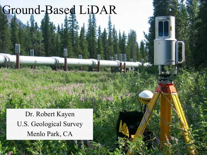
SLIDE 1 Ground-Based LiDAR Ground-Based LiDAR
U.S. Geological Survey Menlo Park, CA
U.S. Geological Survey Menlo Park, CA
SLIDE 2 The Reconnaissance Problem: We want to collect and archive highly detailed, accurate spatial measurements
- f damaged ground and structures, and
do this rapidly, with limited budget? Solution: Tripod-mounted LiDAR The Reconnaissance Problem: We want to collect and archive highly detailed, accurate spatial measurements
- f damaged ground and structures, and
do this rapidly, with limited budget? Solution: Tripod-mounted LiDAR
SLIDE 3 Ground-Based LiDAR Ground-Based LiDAR
LiDAR (Light Detection And Ranging) Portable & light tripod-mounted systems Fixed or Rotating laser-line scanner systems Produces 3-D target positions at up to 500k positions/minute Range: Up To 1 kilometer around Tripod under optimal atmospheric conditions LiDAR (Light Detection And Ranging) Portable & light tripod-mounted systems Fixed or Rotating laser-line scanner systems Produces 3-D target positions at up to 500k positions/minute Range: Up To 1 kilometer around Tripod under optimal atmospheric conditions
QuickTime™ and a TIFF (Uncompressed) decompressor are needed to see this picture.
Distance = (Speed of Light x Time of Flight) / 2
SLIDE 4
LiDAR & GEER: Bringing damage ground and structural morphologies back to the lab for analysis, and as a permanent record of event effects. LiDAR & GEER: Bringing damage ground and structural morphologies back to the lab for analysis, and as a permanent record of event effects.
Rapid data collection of damaged terrain. Ultra-high accuracy terrain models for deformation calculations and change detection . Archive-quality spatial models of damage. 3-D spatial visuals and fly-through videos for engineering analysis and public outreach. Rapid data collection of damaged terrain. Ultra-high accuracy terrain models for deformation calculations and change detection . Archive-quality spatial models of damage. 3-D spatial visuals and fly-through videos for engineering analysis and public outreach.
SLIDE 5
USGS-GD Unit: Riegl z210i USGS-GD Unit: Riegl z210i USGS-WRD Unit: Optech ILRIS-3D USGS-WRD Unit: Optech ILRIS-3D
SLIDE 6 LiDAR Systems at the USGS LiDAR Systems at the USGS
OpTech ILRIS-3D Narrow window High-Res Mapper
Accuracy 0.3-0.4 cm
15 minutes
40° by 40°
USGS-Water Resources Division System
Riegl z210i General Purpose Mapper:
Accuracy 0.9 cm
11 minutes
by 336°
USGS-Geologic Division System
SLIDE 7 Denali Fault offset at Trans Alaska Pipeline, 7/2004: Single Riegl z210i Scan range 580m Denali Fault offset at Trans Alaska Pipeline, 7/2004: Single Riegl z210i Scan range 580m
SLIDE 8 LiDAR Systems at the USGS LiDAR Systems at the USGS
OpTech ILRIS-3D Narrow window High-Res Mapper
Accuracy 0.3-0.4 cm
1.8M in 15 minutes
40° by 40°
USGS-WRD System
Riegl z210i General Purpose Mapper:
Accuracy 0.9 cm
5.6M in 11 minutes
by 336°
USGS-GD System
SLIDE 9 Point Resolution
Spacing : ~2mm near tripod with 9mm 3-D resolution
Point Resolution
Spacing : ~2mm near tripod with 9mm 3-D resolution Fissure Fissure
~30 cm
Parkfield 10/4/04
Traditional post- slip survey marks
SLIDE 10
Parkfield 10/4/2004 Sub-cm 3-D spatial deformation measurements of minor or significant damage at distances up to 700-1000m Minor Fissures Minor Fissures
SLIDE 11 LiDAR Data Processing LiDAR Data Processing
OpTech ILRIS-3D Multiple scans to expand scan window & eliminate shadow zones. Merge point cloud data, produce triangulated surface (TIN) with PolyWorks.
USGS-WRD System
Riegl z210i Single or Multiple scans. Merge point cloud data with I-Site3D Triangulated surface (TIN) for measurement and change detection using I-Site3D
USGS-GD System
SLIDE 12
Merging scans to eliminate shadow zones Merging scans to eliminate shadow zones
Example: single scan of 50- 60 cm Denali Fault scarp. Example: single scan of 50- 60 cm Denali Fault scarp.
10 m
SLIDE 13
Denali Fault: Merge of 2 scans to produce fewer shadow (no data) zones in surface model. High quality DGPS geo-referencing needed for merge.
SLIDE 14
Denali Fault: Merging of 8 scans to produce a largely shadow free surface model of rupture Denali Fault: Merging of 8 scans to produce a largely shadow free surface model of rupture
SLIDE 15 Collins & Sitar, 2003, AEG Ann. Mtg.
TIN surfaces ready for change detection analysis
SLIDE 16
Summary Summary
GEER-EERI-USGS can utilize ground-based LiDAR to collect damage morphology data at speeds, accuracies, and range that was previously unimaginable in earthquake reconnaissance. These permanently archived terrain models will vastly improve controls on empirical deformation studies and allow researchers decades later to virtually-revisit damage sites. GEER-EERI-USGS can utilize ground-based LiDAR to collect damage morphology data at speeds, accuracies, and range that was previously unimaginable in earthquake reconnaissance. These permanently archived terrain models will vastly improve controls on empirical deformation studies and allow researchers decades later to virtually-revisit damage sites.
SLIDE 17 Ground-Based LiDAR Ground-Based LiDAR
U.S. Geological Survey Menlo Park, CA
U.S. Geological Survey Menlo Park, CA