FSM$Modeling State$Diagrams$(SDs)$and$Algorithmic$State$ - - PDF document

fsm modeling
SMART_READER_LITE
LIVE PREVIEW

FSM$Modeling State$Diagrams$(SDs)$and$Algorithmic$State$ - - PDF document

FSM$Modeling State$Diagrams$(SDs)$and$Algorithmic$State$ Machine$(ASM)$charts$Describe$Behavior$of$FSMs Translating$Directly$from$SD/ASMs$to$Verilog$is$ Advantageous No$Worry$about$Mistake$in$Logic$Simplification


slide-1
SLIDE 1

FSM$Modeling

  • State$Diagrams$(SDs)$and$Algorithmic$State$

Machine$(ASM)$charts$Describe$Behavior$of$FSMs

  • Translating$Directly$from$SD/ASMs$to$Verilog$is$

Advantageous

– No$Worry$about$Mistake$in$Logic$Simplification – No$Tedious$Tables$to$Create – Automatic$Tools$(synthesis)$Create$the$Schematic$ Directly – Synthesis$Tools$can$Handle$Very$Large$FSMs$(100s$ even$1000s$of$DFFs) – Can$EASILY$Change$State$Assignment

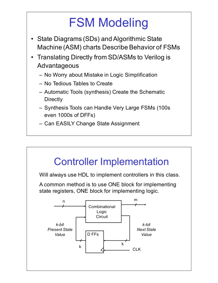
Controller$Implementation

Will$always$use$HDL$to$implement$controllers$in$this$class. A$common$method$is$to$use$ONE$block$for$implementing$ state$registers,$ONE$block$for$implementing$logic.

Combinational Logic Circuit D$FFs n m k k k"bit Present+State Value k"bit Next+State Value CLK

slide-2
SLIDE 2

Controller$Block$Diagrams

Blocking/NonSblocking$Example

  • Assume$Initially$A=1,$B=2,$C=3
  • Assume$the$Following$are$Within$Blocks:

B = A; C = B + 1; B <= A; C <= B + 1; Blocking Non"Blocking

  • When$Blocking$statements$finish$Simulation:

A=1,$B=1,$C=2

  • When$NonSBlocking$statements$finish$Simulation:

A=1,$B=1,$C=3

slide-3
SLIDE 3

Blocking/NonSblocking$Example

  • Consider$the$Following$Blocks:

begin A = B; B = A; end begin A <= B; B <= A; end Blocking+Statements Non"Blocking+Statements

  • When$Blocking$statements$finish$Simulation:

A and$B both$end$up$with$the$value$originally$in B

  • When$NonSBlocking$statements$finish$Simulation:

RHS$of$assignments$first$collected$into$temporary$storage A and$B content$is$interchanged This$gives$the$effect$of$concurrency

Synthesis$Example

D Q D Q D Q D Q A A B B Y Y clk clk

always @ (posedge clk) begin A = Y; B = A; end always @ (posedge clk) begin A <= Y; B <= A; end always @ (posedge clk) begin B = A; A = Y; end *example from Franzon/Smith book

slide-4
SLIDE 4

Blocking/NonSblocking$Rules

  • Blocking$versus$NonSblocking$statements$can$Produce$

Different$Synthesized$Circuits

  • Use$NonSblocking$Statements$in$always$Blocks$that$model$

Sequential$Logic

  • Use$Blocking$Statements$in$always$Blocks$that$model$

Combinational$Logic

  • Do$Not$Mix$Blocking$and$NonSblocking$statements$in$a$

Single$always$Block

  • Reasons$are$Subtle$and$Have$to$do$with$Internal$Simulator$

Queue$Scheduling

  • NonSadherence$to$these$rules$can$Lead$to$Race$

Conditions$or$Inference$of$Incorrect$Logic

  • See$Link$to$Paper$for$Details

One$always Block$Style

Single$always Block Models$This$Part Concurrent$Assignments Model$This$Part

slide-5
SLIDE 5

Verilog$Controller$with$Single$Always$ Block$(Part$1)

module ramfsm_ex1 (state, addr_sel, cnt_en, ld_cnt, zero_we, set_busy, clr_busy, clk, reset, zero, cnt_eq); input clk, reset, zero, cnt_eq;

  • utput [1:0] state; //state output for debugging
  • utput addr_sel, cnt_en, ld_cnt, zero_we;
  • utput set_busy, clr_busy;

reg [1:0] state; // State Encoding Here parameter S0=2'b00, S1=2'b01, S2=2'b10;

Memory$Zeroing$ASM$Chart

slide-6
SLIDE 6

Verilog$Controller$with$Single$Always$ Block$(Part$2)

// Register and Combinational Transition logic here always @(posedge clk or posedge reset) begin if (reset == 1'b1) state<=S0; else case (state) S0: if (zero == 1'b1) state <= S1; S1: state <= S2; S2: if (cnt_eq == 1'b1) state <= S0; default: state <= S0; endcase end // Combinational output logic here assign set_busy = (state==S0 && zero==1'b1) ? 1'b1 : 1'b0; assign ld_cnt = (state==S1) ? 1'b1 : 1'b0; assign addr_sel = (state==S2) ? 1'b1 : 1'b0; assign zero_we = (state==S2) ? 1'b1 : 1'b0; assign cnt_en = (state==S2) ? 1'b1 : 1'b0; assign clr_busy = (state==S2 && cnt_eq==1'b1) ? 1'b1 : 1'b0; endmodule

One$Process$VHDL$Version

library ieee; use ieee.std_logic_1164.all;

  • - FSM entity for RAM Zero example

entity ramfsm is port ( clk, reset: in std_logic; zero, cnt_eq: in std_logic; -- control inputs set_busy, clr_busy: out std_logic; -- control outputs addr_sel, cnt_en, ld_cnt, zero_we: out std_logic; state: out std_logic_vector(1 downto 0) -- state out for debugging ); end ramfsm; architecture a of ramfsm is signal pstate: std_logic_vector(1 downto 0);

  • - state encoding

CONSTANT S0 : std_logic_vector(1 downto 0) := "00"; CONSTANT S1 : std_logic_vector(1 downto 0) := "01"; CONSTANT S2 : std_logic_vector(1 downto 0) := "10";

slide-7
SLIDE 7

One$Process$VHDL$Version$(cont)

begin state <= pstate; -- look at present state for debugging purposes stateff:process(clk) -- process has state transistions ONLY begin if (reset = '1') then pstate <= S0; elsif (clk'event and clk='1') then -- rising edge of clock CASE pstate IS WHEN S0 => if (zero = '1') then pstate <= S1; end if; WHEN S1 => pstate <= S2; WHEN S2 => if (cnt_eq = '1') then pstate <= S0 ; end if; WHEN others => pstate <= S0; end case; end if; end process stateff; set_busy <= '1' when (pstate = S0 and zero = ‘1’) else '0'; ld_cnt <= '1' when (pstate = S1) else '0'; addr_sel <= '1' when (pstate = S2) else '0'; zero_we <= '1' when (pstate = S2) else '0'; cnt_en <= '1' when (pstate = S2) else '0'; clr_busy <= '1' when (pstate = S2 and cnt_eq = '1') else '0'; end a;

Comments$on$One$always$Block$ Implementation

  • always block$defines$state$FFs$and$transitions$

between$states

  • Outputs$of$controller$are$separate$concurrent$

statements$outside$of$synchronous$block

  • Can$be$confusing$since$you$separate$out$the$FSM$
  • utputs$from$their$state$definitions$within$the$

CASE$statement

slide-8
SLIDE 8

Two$always Blocks$Style

Second$always Block Models$These$Parts First$always Block Models$This$Part

Controller$Verilog$with$Two$Always$Blocks$ (Part$1)

module ramfsm_ex2 (pstate, addr_sel, cnt_en, ld_cnt, zero_we, set_busy, clr_busy, clk, reset, zero, cnt_eq); input clk, reset, zero, cnt_eq;

  • utput [1:0] pstate; //state output for debugging
  • utput addr_sel, cnt_en, ld_cnt, zero_we;
  • utput set_busy, clr_busy;

reg addr_sel, cnt_en, ld_cnt, zero_we, set_busy, clr_busy; reg [1:0] pstate, nstate; // State Encoding Here parameter S0=2'b00, S1=2'b01, S2=2'b10; // Register logic here always @(posedge clk or posedge reset) begin if (reset == 1'b1) pstate <= S0; else pstate <= nstate; end

slide-9
SLIDE 9

Controller$Verilog$with$Two$Always$Blocks$

(Part$2)

// Combinational transition and output logic here always @(pstate or zero or cnt_eq) begin // We must include default values here // to avoid inferred latches set_busy = 1'b0; ld_cnt = 1'b0; clr_busy = 1'b0; addr_sel = 1'b0; zero_we = 1'b0; cnt_en = 1'b0; // Transition and output logic in case statement case (pstate) S0: if (zero == 1'b1) begin nstate = S1; set_busy = 1'b1; end else nstate = S0;

Controller$Verilog$with$Two$Always$Blocks

(Part$3)

S1: begin nstate = S2; ld_cnt = 1'b1; end S2: begin if (cnt_eq == 1'b1) begin nstate = S0; clr_busy = 1'b1; end else nstate = S2; addr_sel = 1'b1; zero_we = 1'b1; cnt_en = 1'b1; end default: nstate = S0; endcase end endmodule

slide-10
SLIDE 10

Two$Process$VHDL$Version

architecture a of ramfsm is signal pstate, nstate: std_logic_vector(1 downto 0);

  • - state encoding

CONSTANT S0 : std_logic_vector(1 downto 0) := "00"; CONSTANT S1 : std_logic_vector(1 downto 0) := "01"; CONSTANT S2 : std_logic_vector(1 downto 0) := "10"; begin state <= pstate; -- look at present state for debugging purposes stateff:process(clk) -- process has DFFs only begin if (reset = '1') then pstate <= S0; elsif (clk'event and clk='1') then pstate <= nstate; -- update pres. w. next state endif; end process stateff;

Two$Process$VHDL$Version

comblogic: process (zero, cnt_eq, pstate) begin

  • - default assignments

nstate <= pstate; set_busy <= '0'; clr_busy <= '0'; ld_cnt <= '0'; addr_sel <= '0'; zero_we <= '0'; cnt_en <= '0'; CASE pstate IS WHEN S0 => if (zero = '1') then set_busy <= ‘1’; nstate <= S1; end if; WHEN S1 => ld_cnt <= ’1'; nstate <= S2; WHEN S2 => zero_we <= '1'; cnt_en <= '1' ; addr_sel <= '1’; if (cnt_eq = '1') then clr_busy <= '1’; nstate <= S0 ; end if; WHEN others => nstate <= S0; end case; end if; end process comblogic; end a;

slide-11
SLIDE 11

Comments$on$Two$always$block$ Implementation

  • First$always block$process$defines$only$FFs
  • Second$always block$defines

– State$transitions – Output$assertions – Has$natural$mapping$from$ASM$chart$to$CASE$statement

  • Default$assignments$to$outputs$in$Combinational$

always Block$(VHDL$Comblogic$process)$very$ important$to$Prevent$Inferred$Latches

Two$always Blocks$with$Concurrent$ Output$Logic$Style

Second$always Block Models$This$Part First$always Block Models$This$Part Concurrent$Assignments Model$This$Part

slide-12
SLIDE 12

Controller$Verilog$with$Two$Always$Blocks$ and$Concurrent$Logic$(Part$1)

module ramfsm_ex3 (pstate, addr_sel, cnt_en, ld_cnt, zero_we, set_busy, clr_busy, clk, reset, zero, cnt_eq); input clk, reset, zero, cnt_eq;

  • utput [1:0] pstate; //state output for debugging
  • utput addr_sel, cnt_en, ld_cnt, zero_we;
  • utput set_busy, clr_busy;

reg [1:0] pstate, nstate; // State Encoding Here parameter S0=2'b00, S1=2'b01, S2=2'b10; // Register logic here always @(posedge clk or posedge reset) begin if (reset == 1'b1) pstate<=S0; else pstate <= nstate; end

Controller$Verilog$with$Two$Always$Blocks$ and$Concurrent$Logic$(Part$2)

// Combinational transition logic here always @(pstate) begin case (pstate) S0: if (zero == 1'b1) nstate = S1; else nstate = S0; S1: nstate = S2; S2: if (cnt_eq == 1'b1) nstate = S0; else nstate = S2; default: nstate = S0; endcase end

slide-13
SLIDE 13

Controller$Verilog$with$Two$Always$Blocks$ and$Concurrent$Logic$(Part$3)

// Combinational output logic here assign set_busy = (pstate==S0 && zero==1'b1) ? 1'b1 : 1'b0; assign ld_cnt = (pstate==S1) ? 1'b1 : 1'b0; assign addr_sel = (pstate==S2) ? 1'b1 : 1'b0; assign zero_we = (pstate==S2) ? 1'b1 : 1'b0; assign cnt_en = (pstate==S2) ? 1'b1 : 1'b0; assign clr_busy = (pstate==S2 && cnt_eq==1'b1) ? 1'b1 : 1'b0; endmodule

FSM$Timing:$Start$Zero$Operation

CLK Pstate Nstate S0 S0 S1 S1 S2 Zero (ext. Input) S2 Set_busy Ld_cnt Zero_we, cnt_en, addr_sel Busy (external output)

slide-14
SLIDE 14

FSM$Timing:$Finish$Zero$Operation

CLK Pstate Nstate S2 S2 S0 S0 Cnt_Eq (from Comparator) Clr_busy Zero_we, cnt_en, addr_sel Busy (external output) Counter High-2 High+1 High-1 High

Controller$Block$Diagrams

slide-15
SLIDE 15

Comments

  • Note$that$pstate changes$on$active$clock$edge
  • Conditional$outputs$will$change$based$on$

present$state$AND$external$inputs

  • Unconditional$outputs$change$on$clock$edge$

and$remain$true$as$long$as$in$the$current$state

  • In$order$for$busy to$go$high$in$State$S1,$

‘set_busy’$must$be$asserted$in$S0 since$busy comes$from$JK$FF.

Comments

  • Note$that$for$busy$to$go$low$in$S0,$then$

“clr_busy”$had$to$be$asserted$in$State$S2.

  • Note$that$the$‘cnt_en’$signal$stays$true$for$
  • ne$clock$edge$after$$‘cnt_eq’$goes$true

– This$means$that$the$COUNTER$will$increment$to$ HIGH+1,$sometimes$this$makes$a$difference,$ need$to$be$aware$of$it

slide-16
SLIDE 16

Synthesized$Controller$Logic

Mealy$versus$Moore

  • Previous$3$Styles$of$Controller$HDL$

Synthesize$to$Circuitry$with$Identical$ Input/Output$Behavior

  • Can$Transform$Mealy$Model$to$Moore$Model
  • Timing$Behavior$Changes$Since$Outputs$

Change$Only$at$Clock$Edges

  • May$or$May$Not$be$Desirable$to$Utilize$a$

Moore$Model$Implementation

slide-17
SLIDE 17

Memory$Zeroing$State$Diagram

Mealy$Controller$Model

Mealy$to$Moore$Conversion

slide-18
SLIDE 18

Memory$Zeroing$State$Diagram

Moore$Controller$Model

Symbolic+States State+Values+Assigned in+Bold

One$always Block$with$Concurrent$ Output$Logic$Style

always Block Models$These$Parts Concurrent$Assignments Model$This$Part

slide-19
SLIDE 19

Controller$Verilog$Implemented$as$Moore$ Machine$(Part$1)

module ramfsm_ex4 (state, addr_sel, cnt_en, ld_cnt, zero_we, set_busy, clr_busy, clk, reset, zero, cnt_eq); input clk, reset, zero, cnt_eq;

  • utput [6:0] state; //state output for debugging
  • utput addr_sel,

cnt_en, ld_cnt, zero_we;

  • utput set_busy,

clr_busy; reg [6:0] state; // State Encoding Here parameter A=7'b0000000, B=7'b0101000, C=7'b0000111, D=7'b1000111 , E=7'b0010000; // Register and Combinational Transition logic here always @(posedge clk or posedge reset) begin if (reset == 1'b1) state<=A; else case (state) A: if (zero == 1'b1) state <= B; else state <= A; B: state <= C; C: state <= D;

Controller$Verilog$Implemented$as$ Moore$Machine$(Part$2)

slide-20
SLIDE 20

D: if (cnt_eq == 1'b1) state <= E; else state <= D; D: state <= E; E: state <= A; default: state <= A; endcase end

Controller$Verilog$Implemented$as$ Moore$Machine$(Part$3)

// Outputs are directly the state // encoding signals assign set_busy = state[5]; assign clr_busy = state[4]; assign ld_cnt = state[3]; assign addr_sel = state[2]; assign zero_we = state[1]; assign cnt_en = state[0]; endmodule

Controller$Verilog$Implemented$as$ Moore$Machine$(Part$4)

slide-21
SLIDE 21

Verilog$Coding$Guidelines

  • 1. Use$blocking$assignments$(“=”)$in$always

blocks$that$are$meant$to$represent$ combinational$logic.

  • 2. Use$nonSblocking$assignments$(“<=”)$in$always$

blocks$that$are$meant$to$represent$sequential$ logic.

  • 3. Do$not$mix$blocking$and$nonSblocking$

assignments$in$the$same$always block.$If$an$ always block$contains$a$significant$amount$of$ combinational$logic$that$requires$intermediate$ wires$(and$thus,$intermediate$assignments),$ then$place$this$logic$in$a$separate$always block.

Verilog$Coding$Guidelines$(Cont.)

  • 4. If$an$always block$for$combinational$logic$

contains$complicated$logic$pathways$due$to$if" else branching$or$other$logic$constructs,$then$ assign$every$output$a$default$value$at$the$ beginning$of$the$block.$This$ensures$that$all$

  • utputs$are$assigned$a$value$regardless$of$the$

path$taken$through$the$logic,$avoiding$inferred$ latches$on$outputs.$

  • 5. Do$not$make$assignments$to$the$same$output$

from$multiple$always blocks.

slide-22
SLIDE 22

Synthesis$Tool$Warnings

“Input X is unused (does not drive any logic)”

  • This$means$that$the$synthesized$logic$does$not$make$use$
  • f$a$particular$input.

“Output X is stuck at VDD (or GND)”

  • This$means$that$in$the$synthesized$logic$there$is$an$output$

that$has$been$reduced$to$a$fixed$‘1’$or$‘0’$with$no$gating. “Outputs X and Y share the same net”

  • This$means$that$the$logic$for$outputs$X and$Y is$the$same,$

and$that$outputs$X and$Y are$driven$by$the$same$gate.

Synthesis$Tool$Warnings$(cont)

“Output X has no driver”

  • This$means$that$an$output$has$never$been$assigned,$

and$thus$no$logic$has$been$synthesized$to$drive$it. “Combinational loop detected on net X”

  • This$means$that$the$synthesis$tool$has$found$a$

feedback$path$from$a$combinational$gate$output$back$to$

  • ne$of$its$inputs$without$an$intervening$latch$or$DFF.
  • Unless$an$asynchronous (i.e,$no$clock$is$used)$digital$

system$is$being$designed,$this$is$an$error$in$coding$as$ all$feedback$paths$should$be$broken$by$a$sequential$ element.

slide-23
SLIDE 23

Combinational$Loops

3$always Blocks$FSM$Modeling$ Approach

  • Basic$Construct$is$case Statement$within$an$

always Block

  • Can$Internally$Keep$two$regs,$Prstate and$

Nxtstate

  • Use$Three$always blocks$(another$way$to$do$it)

– Interact$by$causing$events$in$different$blocks – first$always block$handles$asynchronous$and$ synchronous$events – second$always block$determines$the$next$state – third$always block$evaluates$output$signals

slide-24
SLIDE 24

Verilog$FSM$Behavioral$Model$Example

Mealy+Machine

Verilog$FSM$Model$Example

//HDL Example 5-5 (adapted-MAT) //--------------------------------- //Mealy state diagram (Fig 5-16) module Mealy_mdl (x,y,CLK,RST); input x,CLK,RST;

  • utput y;

reg y; reg [1:0] Prstate, Nxtstate; parameter S0 = 2'b00, S1 = 2'b01, S2 = 2'b10, S3 = 2'b11; always @ (posedge CLK or negedge RST) // Clocked block if (~RST) Prstate <= S0; //Initialize to state S0 else Prstate <= Nxtstate; //Clock operations always @ (Prstate or x) //Determine next state case (Prstate) //Transition Functions S0: if (x) Nxtstate = S1; S1: if (x) Nxtstate = S3; else Nxtstate = S0; S2: if (~x)Nxtstate = S0; S3: if (x) Nxtstate = S2; else Nxtstate = S0; endcase

slide-25
SLIDE 25

Verilog$FSM$Behavioral$Model$Example

always @ (Prstate or x) //Evaluate output case (Prstate) //Output Functions S0: y = 0; S1: if (x) y = 1'b0; else y = 1'b1; S2: if (x) y = 1'b0; else y = 1'b1; S3: if (x) y = 1'b0; else y = 1'b1; endcase endmodule

Verilog$FSM$Behavioral$Model$Example

Moore+Machine

S0

(00)

S1

(01)

S2

(10)

S3

(11)

1 1 1 1

slide-26
SLIDE 26

Verilog$FSM$Behavioral$Model$Example

Moore+Machine

//HDL Example 5-6 (adapted-MAT) //----------------------------------- //Moore state diagram (Fig. 5-19) module Moore_mdl (x,AB,CLK,RST); input x,CLK,RST;

  • utput [1:0]AB;

reg [1:0] state; parameter S0 = 2'b00, S1 = 2'b01, S2 = 2'b10, S3 = 2'b11; always @ (posedge CLK or negedge RST) if (~RST) state <= S0; //Initialize to state S0 else // Clocked block and Transition Logic case (state) S0: if (~x) state <= S1; else state <= S0; S1: if (x) state <= S2; else state <= S3; S2: if (~x) state <= S3; else state <= S2; S3: if (~x) state <= S0; else state <= S3; endcase assign AB = state; //Output Function endmodule