
SLIDE 1
iBNCT Project ct
- H. Kumada, K. Takada, T. Aihara, A. Matsumura
- H. Sakurai, T. Sakae
for boron neutron capture therapy H. Kumada , K. Takada, T. Aihara, - - PowerPoint PPT Presentation
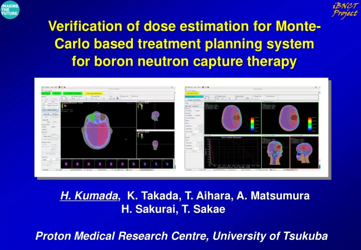
iBNCT Project ct Verification of dose estimation for Monte- Carlo based treatment planning system for boron neutron capture therapy H. Kumada , K. Takada, T. Aihara, A. Matsumura H. Sakurai, T. Sakae Proton Medical Research Centre,
iBNCT Project ct
iBNCT Project ct
Kyoto University Research Reactor Institute (Osaka) National Cancer Center Hospital (Tokyo) Southern Tohoku BNCT Research Center (Fukushima) University of Tsukuba (Ibaraki)
iBNCT Project ct
【RFQ+DTL Type Linac for BNCT】 【Treatment Management System】
《Beam Transport System》
《Patient Positioning System》
《PG-SPECT》 《Neutron Monitor》
Proton Beam
Neutron Beam
《Neutron Generator》 《Beryllium Target》 スペクトル可変機構 中性子ターゲット 中性子 即発γ線検出器 と中性子反応で生じる即発γ線
即発γ線 ベース・リアルタイム3 線量モニター
中性子遮蔽壁
陽子線
【Treatment Planning System】
Treatment room Linac
iBNCT Project ct
Monte-Carlo Calculation
iBNCT Project ct
iBNCT Project ct
1st scatterer MLC Middle collimator Bolus Ridge filter 2nd scatterer Head phantom
Proton therapy in University
6 MV
Irradiation field: 5 cm×5 cm
0.0% 20.0% 40.0% 60.0% 80.0% 100.0% 120.0% 0.0 100.0 200.0 Relative dose Depth in water (mm) Measured data PHITS calculation 0.0% 20.0% 40.0% 60.0% 80.0% 100.0% 120.0%
Relative dose Distance from the beam axis(mm) Measured data PHITS calculation
Comparison results of PDD and OCR for 6-MV beam
T arget Region
X-ra y Bea m D i r e c t i o n
Two-field fractionated X-ray irradiation
Measure Depth:90 mm
SOBP:40 mm
0.0% 20.0% 40.0% 60.0% 80.0% 100.0% 120.0% 0.0 50.0 100.0 150.0 Rela tive dose Depth in water (mm) Measurement data PHITS calculation
2D dose distribution
Target Region
Poster No. 124: H. Kumada, et al., “Application expansion of the Monte-Carlo based treatment planning system for BNCT to particle radiotherapy and X-ray therapy.”
Secondary neutron dose estimation in Proton therapy Proton dose distributions Secondary neutron dose distributions
Poster No. 125: K. Takada, et al., “Fundamental study for practical application of radiotherapy treatment planning system capable of evaluation neutron dose generated by various radiotherapy beams.”
iBNCT Project ct
iBNCT Project ct
Southern Tohoku Hospital, BNCT Center National Cancer Center Hospital
Irradiation room Accelerator
Kyoto University KUR, BNCT facility University of Tsukuba, iBNCT Facility
iBNCT Project ct
iBNCT accelerator-based neutron source for BNCT in University of Tsukuba
Water phantom
Beam Port
Water Phantom
KUR in Kyoto University Research Reactor
Water Phantom
Thermal neutron flux distributions in a cylindrical water phantom
0.0E+00 5.0E+08 1.0E+09 1.5E+09 2.0E+09 2.5E+09 3.0E+09 3.5E+09 0.0 1.0 2.0 3.0 4.0 5.0 6.0 7.0 8.0 9.0 10.0
Thermal Neutron Flux (n/cm2s) Depth from phantom surface (cm) グラフ タイトル
Experimental Values Tsukuba Plan Calculations
iBNCT Project ct
Experiments in iBNCT facility in Univ. Tsukuba
Water phantom experiments
0.0E+00 2.0E+07 4.0E+07 6.0E+07 8.0E+07 1.0E+08 1.2E+08 0.0 1.0 2.0 3.0 4.0 5.0 6.0 7.0 8.0 9.0 10.0
熱中性子束 (n/cm2・s)
Phantom 表面からの深さ (cm) 陽子電流:平均 A 水ファントム実験結果
金箔実験値 LiCAF実験値 モンテカルロ計算値
Dose estimations by using Tsukuba Plan 3D-Model of water phantom Thermal neutron flux distributions Calculation Model
Compare
iBNCT Project ct
Calculation time
0.0E+00 1.0E+08 2.0E+08 3.0E+08 4.0E+08 5.0E+08 6.0E+08 7.0E+08 8.0E+08 9.0E+08
0.0 2.0 4.0 6.0 8.0 10.0
Thermal Neutron Flux (n/cm2s)
Depth from surface (cm)
Calculations Measurements
0.0E+00 5.0E+07 1.0E+08 1.5E+08 2.0E+08 2.5E+08 3.0E+08 3.5E+08 4.0E+08 4.5E+08 5.0E+08
0.0 2.0 4.0 6.0 8.0 10.0
Thermal Neutron Flux (n/cm2s) Distance from center (cm)
Calculations Surface Measurements Surface Calculations Depth 0.5cm Meaurements Depth 0.3cm
Beam central axis Lateral distributions
surface
Depth from surface: 0.5cm
0.0E+00 5.0E+07 1.0E+08 1.5E+08 2.0E+08 2.5E+08 3.0E+08 3.5E+08 4.0E+08 4.5E+08 5.0E+08
0.0 2.0 4.0 6.0 8.0 10.0
Thermal Neutron Flux (n/cm2s) Distance from center (cm)
Calculations Surface Measurements Surface Calculations Depth 0.5cm Meaurements Depth 0.3cm
surface
Depth from surface: 0.5cm Normalization point: Depth: 5cm
0.5
0.0E+00 5.0E-01 1.0E+00 1.5E+00 2.0E+00 2.5E+00 3.0E+00 3.5E+00 4.0E+00
0.0 2.0 4.0 6.0 8.0 10.0
Gamma-ray dose rate (Gy/h)
Depth from surface (cm)
Calculation Measurements
0.0E+00 5.0E-01 1.0E+00 1.5E+00 2.0E+00 2.5E+00 3.0E+00 3.5E+00 4.0E+00
0.0 2.0 4.0 6.0 8.0 10.0
Gamma-ray dose rate (Gy/h) Distance from center (cm)
Calculation Surface Measurements Surface Calculation Depth 2cm Measurements Depth 2cm Calculation Depth 2cm Measurements 10cm
Beam central axis Lateral distributions
surface
Depth: 2cm Depth: 10cm
10
iBNCT Project ct
Calculation models Calculation Results Set irradiation conditions Set ROI and target point
iBNCT Project ct
10 20 30 40 50 60 70 80 90 100
0.0 10.0 20.0 30.0 40.0 50.0 60.0 70.0 80.0 グラ フ タ イ ト ル iBNCT Left Brain KUR Left Brain JRR-4 Left Brain JRR412cmBeam Left Brain iBNCT Tumor KUR Tumor JRR-4 Tumor JRR412cmBeam Tumor
Volume(%) Dose(Gy-Eq) iBNCT Source・Tumor KUR Source・Tumor JRR4, 10cm port・Tumor JRR4, 12cm port・Tumor
iBNCT Project ct
Dose estimation for whole body exposure using Tsukuba-Plan
Near future
Measurement for whole body exposure in BNCT using a whole body phantom Dose estimation for whole body exposure in BNCT irradiation using PHITS
人体フ ァ ント ム照射シミ ュ レーショ ンモデル 熱中性子束 次元分布計算結果
人体フ ァ ント ム ビーム孔
At the moment
iBNCT Project ct