Filtering Based Techniques DDOS Attacks: Target CPU / Bandwidth - - PDF document

filtering based techniques
SMART_READER_LITE
LIVE PREVIEW

Filtering Based Techniques DDOS Attacks: Target CPU / Bandwidth - - PDF document

Introduction: Filtering Based Techniques DDOS Attacks: Target CPU / Bandwidth for DDOS Mitigation Attacker signals slaves to launch an attack on a specific target address (victim). Slaves then respond by Comp290: Network


slide-1
SLIDE 1

Filtering Based Techniques for DDOS Mitigation

Comp290: Network Intrusion Detection Manoj Ampalam
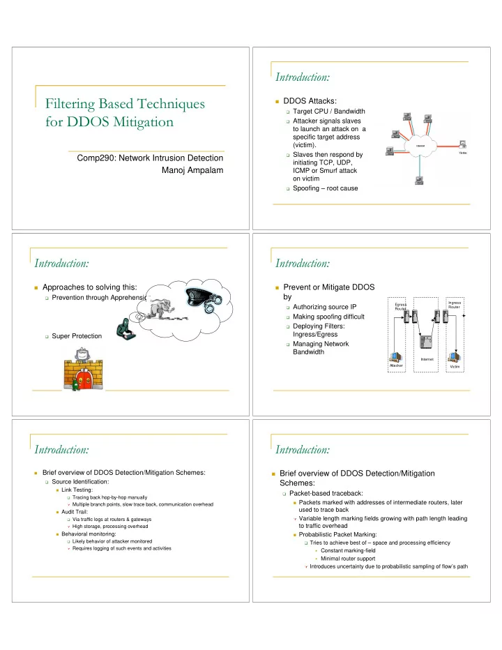
Introduction:

DDOS Attacks:

Target CPU / Bandwidth Attacker signals slaves

to launch an attack on a specific target address (victim).

Slaves then respond by

initiating TCP, UDP, ICMP or Smurf attack

  • n victim

Spoofing – root cause

Introduction:

Approaches to solving this:

Prevention through Apprehension Super Protection

Introduction:

Prevent or Mitigate DDOS

by

Authorizing source IP Making spoofing difficult Deploying Filters:

Ingress/Egress

Managing Network

Bandwidth

Attacker Victim Egress Router Ingress Router Internet

Introduction:

Brief overview of DDOS Detection/Mitigation Schemes:

Source Identification: Link Testing: Tracing back hop-by-hop manually Multiple branch points, slow trace back, communication overhead Audit Trail: Via traffic logs at routers & gateways High storage, processing overhead Behavioral monitoring: Likely behavior of attacker monitored Requires logging of such events and activities

Introduction:

Brief overview of DDOS Detection/Mitigation

Schemes:

Packet-based traceback: Packets marked with addresses of intermediate routers, later

used to trace back

Variable length marking fields growing with path length leading

to traffic overhead

Probabilistic Packet Marking: Tries to achieve best of – space and processing efficiency Constant marking-field Minimal router support Introduces uncertainty due to probabilistic sampling of flow’s path

slide-2
SLIDE 2

Introduction:

Based on the location of deployment:

Router Based Improve routing infrastructure Off-line analysis of flooding traffic traces Doesn’t help sustain service availability during attack On-line filtering of spoofed packets Rely on IP-Router enhancements to detect abnormal patterns No incentive for ISPs to implement these services Administrative overhead Lack of immediate benefit to their customers End-System Based Provide sophisticated resource management to internet servers Doesn’t required router support. Not so effective

Topics for this presentation:

Different Filtering Techniques

Hop-Count Filtering End-System Based Uses Packet Header Information Distributed Packet Filtering Route-based Uses Routing Information D-WARD Source-end network based Uses Abnormal Traffic Flow information Ingress Filtering Specifies Internet Best Current Practices

Hop-Count Filtering

Cheng Jin, Haining Wang, Kang G. Shin, Proceedings of the 10th ACM International Conference on Computer and Communications Security (CCS), October 2003

Hop-Count Filtering:

Motivation:

Most spoofed IP packets when arriving at victims do not

carry hop-count values that are consistent with those of legitimate ones.

Hop-Count distribution of client IP addresses at a server

take a range of values

Hop-Count Filtering: Hop-Count Filtering:

So, how’s hop-count calculated?

Computed based on the 8-bit TTL filed of IP header Introduced originally to specify maximum lifetime of IP packet During transit, each intermediate router decrements the

TTL value of an IP packet before forwarding

The difference between the final value and the initial value is

thus the number of hops taken.

What’s the initial value of TTL field? Is it a constant? NO

slide-3
SLIDE 3

Hop-Count Filtering:

TTL field:

Varies with operating Systems. So do we have to know the type of Operating System before

computing hop-count?

Not Really required Most modern OSs use only few selected initial TTL

values: 30,32,60,64,128 and 256

Its generally believed that few internet hosts are apart by

more than 30 hops

Hence, initial value of TTL is the smallest number in the

standard list greater than the final TTL value

Hop-Count Filtering:

The basic algorithm follows:

Hop-Count Filtering:

The ‘making’ of the HCF Tables:

Objectives:

Accurate IP2HC mapping Up-to-date IP2HC mapping Continuously monitory for legitimate hop-count changes Legitimate – established TCP connections Moderate storage Concept of Aggregation with Hop-Count Clustering

Hop-Count Filtering:

Aggregation with Hop-Count Clustering:

IPs primarily mapped based

  • n 24-bit prefix

IP address further divided

based on hop-count

Nodes aggregated if

hop-count value is same

No two IPs with different

hop-counts aggregated

Not all IPs can be aggregated

Hop-Count Filtering:

Aggregation with Hop-Count Clustering: Effectiveness

Hop-Count Filtering:

Effectiveness:

HCF removes nearly 90% of spoofed traffic Assessed from a mathematical standpoint Assumptions: Victim knows complete IP2HP mapping Attacker randomly selects source IP addresses Static Hop-Count Values Attackers evenly divide flooding traffic

slide-4
SLIDE 4

Hop-Count Filtering:

Effectiveness: For single source simple attack

Hop-count from flooding source to victim – h Fraction of IP having h hop counts to victim – h

Fraction of spoofed IP Addresses that cannot be detected -- h Even when a attacker with Mean HC is considered, h is around 10%

Hop-Count Filtering:

Effectiveness: For multiple (n) source simple attack

Total Flood Packets – F Each attacker generates F/n packets hi - hop count from attacker i to victim hi – fraction of IPs with hopcount hi

Fraction of spoofed IP Addresses that cannot be detected from i-- hi Fraction of non-identifiable spoofed packets = (1/n)hi

Hop-Count Filtering:

Can this filter be outplayed?

What if the attacker manufactures an appropriate initial

TTL value for each spoofed packet?

Should know hop-count between randomized IP and victim. Has to build a priori an IP2HC mapping table at victim. What if the hop-count mapping is found through an

accurate router-level topology of internet?

No such contemporary tools giving accurate topology information. Why choose random-IP? Choose to spoof an IP address

from a set of compromised machines.

Weakens the attacking capability. Will be defeated by currently existing practices.

Sabotage router to alter TTL value? Don’t know how far that’s feasible.

Distributed Packet Filtering

Kihong Park, Heejo Lee, Proceedings of ACM SIGCOMM 2001, San Diego, California, August 2001

DPF: Distributed Packet Filtering

Route based distributed packet filtering

Uses routing information to determine ‘goodness’ of a

arriving packet

Similar to the limitation of firewalls whose filtering rules

reflect access constraints local to the network system being guarded.

Salient features:

Proactively filters out a significant fraction of spoofed

packet flows

Reactively identifies source of spoofed IP flows Takes advantage of the ‘power-law’ structure of the

Internet AS topology.

DPF: Distributed Packet Filtering

Filtering: Main Idea:

Works on a graph of Internet Autonomous Systems (AS) Node 7 uses IP address belonging to node 2 when

attacking node 4

What if a border router belonging AS 6 would recognize

if its cognizant of route topology?

slide-5
SLIDE 5

DPF: Distributed Packet Filtering

Filtering: Issues:

Filtering done at granularity of AS node No filtering on attacks originating within a node An edge in AS graph between pair of nodes – a set of

peering point connections

All border routers mush carry filtering tasks Two IPs belonging to the same node may lead to

different paths on AS topology

Incorporate multi-path routing

DPF: Distributed Packet Filtering

Filtering:

Terminology: Given G=(V,E) representing Internet AS topology (u,v) – set of all loop-free paths from u to v R(u,v) – set of computed routes using a routing algorithm R(u,v) is subset of (u,v) A Filter Fe is a route based packet filter with respect to R if Fe(s,t) = 0

for e belonging to R(s,t)

Fe is a maximal filter if it satisfies Fe(s,t) = 0 iff there exists a

path in R(s,t) with e as one of the links

Fe is a semi-maximal filter with respect to R if

  • =
  • therwise

V v some for v s R e if t s F

i e

, 1 ) , ( , ) , (

DPF: Distributed Packet Filtering

Filtering:

Terminology: Sa,t – set of nodes that an attacker at AS a can use as a spoofed

address to reach t.

With route based filtering at node 8 S1,9 = {0,1,2,3,4,5}

Cs,t – set of nodes that could have sent an IP packet M(s,t) with

spoofed source IP s, which did not get filtered on its way

DPF: Distributed Packet Filtering

DPF Effectiveness:

With no filtering S1,9 = {0,1,2,3,4,5,6,7,8} With route-based filtering at node 8 S1,9 = {0,1,2,3,4,5} With route-based filtering at node 8 & 3 S1,9 = {1,2}

DPF: Distributed Packet Filtering

Performance Metrics:

Proactive: Fraction of AS’s from which no spoofed IP

packet can reach its target.

Reactive: Parameterized by 1, denotes Fraction of

AS’s which upon receiving a spoofed IP packet can localize its true source within sites.

{ }

n S V t a

t a

1 , :

,

  • =
  • {

}

n C V s t

t s

  • =

,

, : ) (

DPF: Distributed Packet Filtering

Evaluation:

Study effectiveness of the Filtering process given: Topology Graph: G 1997-99 Internet AS topologies Artificially generated topologies Subset of nodes where filtering is performed: T Node Selection: Randomly Vertex cover Routing Algorithm: R Multipath Routing Loose R – any of loop free paths taken Tight R – only shortest one considered

slide-6
SLIDE 6

DPF: Distributed Packet Filtering

Evaluation: Maximal Vs Semi-Maximal Filters

I997 Internet Topology:

Reactive Metric Proactive Metric

DPF: Distributed Packet Filtering

Evaluation: Loose Vs Tight Routing

I997 Internet Topology:

Loose Tight

DPF: Distributed Packet Filtering

Evaluation: Impact of Network Topology

Performance difference between Inet and Internet AS

graphs: Reactive Metric Proactive Metric

DPF: Distributed Packet Filtering

Evaluation: Results on a generated Topology

Using Brite Topology Generator with Preferential

Connectivity (PC) parameter: Different PC’s – Different probability density functions Reactive Metric Proactive Metric

DPF: Distributed Packet Filtering

Evaluation: Results without Ingress Filtering

Using 1997-1999 topologies with trusted set T allowing local

DoS attacks including those targeted to other domains Reactive Metric Proactive Metric

DPF: Distributed Packet Filtering

Evaluation: Effect of Multi Path Routing

Based on a routing options. “R=loose” - any loop-free path can be used “R=tight” - shortest path to be used

Reactive Metric Proactive Metric

slide-7
SLIDE 7

D-WARD

Jelena Mirkovic, Gregory Prier, Peter Reiher, 10th IEEE International Conference on Network Protocols, Paris, France, November 2002

D-WARD:

Attacking DDOS at source.

Attack flows can be stopped before they enter

Internet core

Facilitate easier trace back and investigation of

attack

Basic Idea

Monitor incoming and outgoing traffic Detect attack by observing abnormalities Respond to attack by rate limiting

D-WARD:

Architecture:

D-WARD:

Monitoring and attack detection:

Configured with a set of ‘police addresses’ (PA) Monitors two-way traffic at flow granularity

Flow – aggregate traffic between PA set foreign host

Monitors traffic at connection level

Connection – aggregate traffic between 2 IPs (PA and

foreign host) and port numbers

Identify legitimate connections

D-WARD:

Monitoring and attack detection:

Flow Classification

Flow statistics kept in a limited-size hash table as flow

records

Stored at granularity of IP address of host Statistics on three types of traffic: TCP, UDP & ICMP Number of packets sent Bytes sent / received Active Connections

D-WARD:

Monitoring and attack detection:

Normal Traffic Modes TCP: defines TCPrto – maximum allowed ratio of number of packets

sent and received in the aggregate TCP flow to the peer.

ICMP: defines ICMPrto – maximum allowed ratio of number of echo,

time stamp and information request and reply packets sent and received in the aggregate flow to the peer.

UCP: defines nconn – an upper bound on number of allowed connections per

destination

pconn – a lower bound on number of allowed connections per destination UDPrate – maximum allowed sending rate per connection Connection Classification Good if compliant: receive guaranteed good service Bad

slide-8
SLIDE 8

D-WARD:

Attack Response:

Throttling component defines the allowed sending rate for a

particular flow based on the current flow characterization and its aggressiveness.

Borrows ideas from TCP congestion control - Multiplicative

Decrease

Uses following equations:

fdec- fraction of offending sending rate rate – realized sending rate for this flow in previous

  • bservation

rl – current rate limit rateinc- speed of slow-recovery finc- speed of fast-recovery

) * 1 ( * * * * ) , min(

dropped sent sent inc dropped sent sent inc dropped sent sent dec

B B B f rl rl B B B rate rl rl B B B f rate rl rl + + = + + = + =

D-WARD:

Evaluation:

Implemented on a linux software router Simulated different types of attacks Customized traffic mixture Constant rate attack Pulsing attack Increasing rate attack Gradual pulse attack Test Network: Attacker and legitimate client belong to source network and

are part of police address set

Foreign host playing role of victim

D-WARD:

Evaluation: Attack Bandwidth passed to Victim

D-WARD:

Evaluation: Attack Bandwidth passed to Victim

D-WARD:

Evaluation: Total attack traffic forwarded with

respect to attack rate

D-WARD:

Evaluation: Attack Detection Time to Maximum

attack rate

slide-9
SLIDE 9

Network Ingress Filtering

  • P. Ferguson, D. Senie, RFC 2827, May 2000

Ingress Filtering

An RFC document intending to increase security

practices and awareness for internet community

Discusses a simple, effective and straightforward

ingress traffic filter

Ingress Filtering

  • Restricting forged Traffic:

Idea is to eliminate spoofing by restricting downstream network traffic to known, and intentionally

advertised prefixes through an ingress filter

Example:

Filter on ingress link of “router 2” allows only traffic originating from within 204.69.207.0/24 prefix

Router 2 Router 1 Router 3 204.69.207.0/24 attacker 11.0.0.0/8 12.0.0.0/8

Ingress Filtering

Further possible capabilities for networking equipment:

Automatic filtering on remote access servers Check every packet on ingress to ensure user not spoofing

Liabilities

Filtering can break some types of “special services” Example: Mobile IP Traffic from a mobile node not tunneled – source address do not match

with attached network.

This RFC suggests considering alternate methods for

implementing these services

Mobile IP Working Group developed “reverse tunnels” to

accommodate ingress filtering

Thank You !!!