SLIDE 15 Phase Lock with Delay Line Control
Building a general purpose phase lock that will tracking with energy ramp Additionally adding control of Colby delay for added flexibility and potential for automated timing
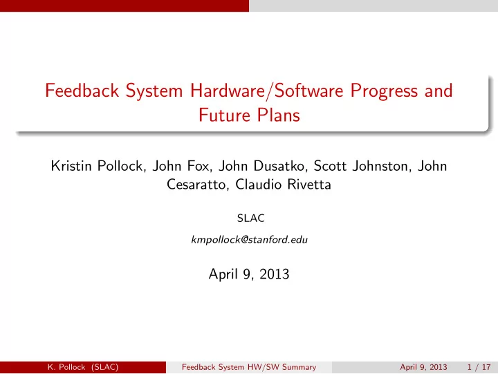
Injection Fiducial USB Interface
Feedback Demonstration System
DAC 400 MHz
D3 D2 Amps DX = Colby Delay lines
RS-232 D2 Control RS-232 D3 control 200MHz locked to SPS signal
Phase Lock + Delay Control Micro- control ler Analog Phase Lock
Revolution Fiducial
Harmonic Multiplier Pickups
SPS 200 MHz 1.6 GHz
Block diagram of phase lock system components.
Injection Fiducial USB Interface DAC 400 MHz RS-232 D2 Control RS-232 D3 control 200MHz locked to SPS signal to Harmonic Multiplier
Phase Lock + Delay Control
Revolution Fiducial SPS 200 MHz x2 Freq Phase Shifter Lo RF LPF ~10MHz Analog Circuitry DC phase
IF Microcontroller or front panel control of edge on which to
- lock. Front panel also displays
whether lock is active and whether it is currently locked.
Microcontroller
At injection fiducial begins counting revolutions and adjusting delays at predetermined rate based on number of turns. Interfaces with computer via USB and colby delays via RS-232.
Diagram of phase lock procedure.
Feedback System HW/SW Summary April 9, 2013 15 / 17