SLIDE 1
February 2010 District 1SR - Navigation Systems Department
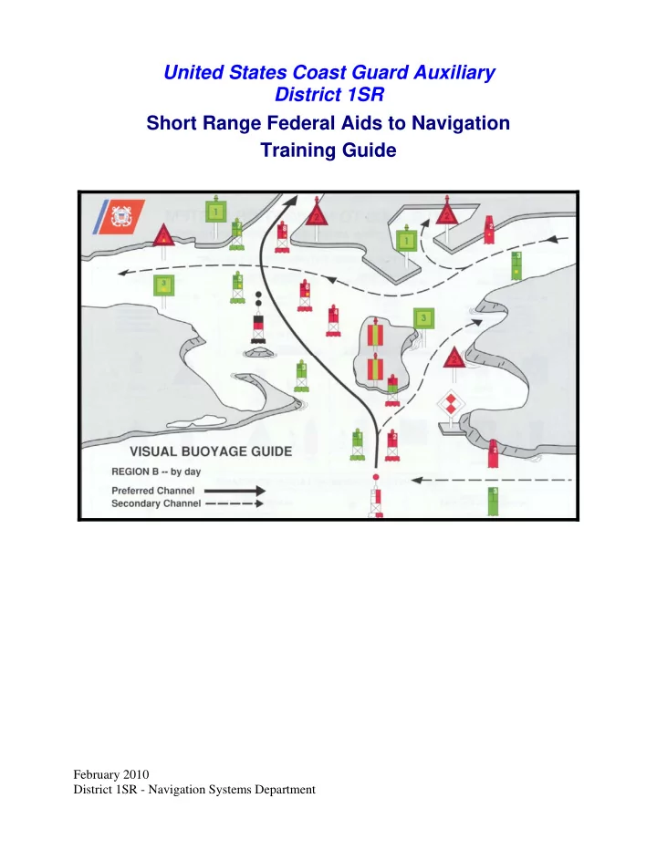
United States Coast Guard Auxiliary District 1SR Short Range Federal Aids to Navigation Training Guide
SLIDE 2 District 1SR Short Range Federal Aid to Navigation Training Guide
February 2010 P a g e 1 District 1SR - Navigation Systems Department
Introduction to Aids to Navigation
One of the primary responsibilities of the Auxiliary Aid to Navigation Program is the reporting of discrepancies observed on Short Range Aids to Navigation (ATONs). The Auxiliary works with the U.S. Coast Guard to accomplish this important mission in a partnership that is focused on assisting the Coast Guard in backwater and remote areas where the Coast Guard doesn’t transit in the normal course of daily operations, as well as the more traveled waterways of the country This “Short Range Federal Aid to Navigation Study Guide” explains the guidelines for checking Aids and for reporting observations of any discrepancies to the local C.G. Units in charge of the maintenance of the aids. Auxiliarists report to the Coast Guard only those discrepancies that they
- bserve on aids. Federal aids found “watching
properly” are normally not reported to the Coast
- Guard. The exception is when a Coast Guard Unit or
agency specifically requests that a particular aid or aids be observed. In addition, when on an authorized patrol, Auxiliarists are able to take credit in AUXDATA for all of their Aid to Navigation activities, whether an aid is observed with a discrepancy or is just found watching properly. The guiding principal here is that it takes a lot of an Auxiliarist’s time and effort to search out a discrepant aid and, therefore, they should receive credit for this mission activity. Review the guidelines for checking a Federal aid on page 30 in this study guide. Conduct all of your aid to navigation activity in a partnership mode with the local CG ANT, Unit or
- ther agency that is responsible for managing the
Federal Aids in your area.
Objectives of this Guide
- To acquire a generalized knowledge of the
specifications for a Short Range Aid to Navigation.
Note: The specific report routing path for a Aid to
Navigation Report is through your Auxiliary ANT
- liaison. It is important to not lose sight of the
primary purpose of this activity, which is always to get the discrepancy report to the Coast Guard Unit that manages the aid as quickly as possible. Processing ATON reports through multi-levels of Auxiliary hierarchy often defeats this objective.
- To develop a familiarity with all of the potential
discrepancies that may be found on a Short Range Aid to Navigation (ATON).
- To become familiar with the Auxiliary guidelines
for checking a Short Range Aid to Navigation
(ATON) properly. This includes the guidelines
for taking and reporting fixes and depths.
- To provide members with an understanding of
the quality standards necessary for operating any electronic equipment used for taking measurements for the ATON program.
- To gain an appreciation for the importance of
reporting all Navigation Systems (NS) activity to AUXDATA for time and activity credits.
Tools needed for checking aids to navigation
The following tools are needed for checking an ATON properly. Usually, this equipment is found aboard an operational facility (OPFAC). However, many Auxiliarists, who participate in the Navigation System’s Programs, often carry a personal navigation kit that contains their personal navigation
- equipment. For a successful aid checking experience, you have to have the right navigational tools, that
are operating accurately, and are available when needed. By including this equipment as part of your pre- underway equipment check, you are helping to guarantee a successful patrol. Pre-calibrate each electronic navigational instrument to insure that it is operating accurately before you get underway.
SLIDE 3 District 1SR Short Range Federal Aid to Navigation Training Guide
February 2010 P a g e 2 District 1SR - Navigation Systems Department Binoculars - Size 7 x 50 are preferred. Binoculars are used to view aids or objects
that maybe located in area where it is unsafe to operate an operational facility
(OPFAC) to order to get a close up view of a potential discrepancies. Many small,
inexpensive and powerful binoculars or monoculars are commercially available and will make a perfect addition to your navigation kit.
Time Piece - A watch or stopwatch is a useful tool for timing the period of an aid’s light.
Any good wristwatch also satisfies this operational need. Your GPS set can provide very accurate date and time information. Report the time when taking fixes and depths alongside
- aids. Set up a GPS screen to show time, Lat/Lon, and EPE (Estimated Position Error). The
screen set up in Figure 1 below is a very handy reference tool for collecting data when locating objects on-scene. Figure 1 – Three-line GPS Screen
Latitude Longitude
42–36-23.50 N 070-23-30.01 W
12.4 ft EPE
Time: 14:45
GPS -
- A GPS set with DGPS (Differential GPS) or WAAS (Wide Area Augmentation
System) can provide location data (Fix) that can be accurate to within 8 to 10 feet. WAAS usually comes as a standard feature on new GPS sets. Ten feet is inside the width of the ordinary OPFAC. If you use one of the fine hand-held GPS models that are currently available, be sure to buy a power cable that plugs into your vessel’s 12v
- power. Also, add spare batteries for your GPS to your navigation kit.
The Light List contains a listing and LAT/LON of most of the aids to navigation in your AOR. Some private aids may not be listed in the Light List. Different Light List volumes are available depending on your geographic
- location. Links to the Light List are available on the ATON page of the
Navigation Systems Web Site – www.USCGAux1SR-ATON.org. Print out
- nly those pages that relate to the area where you operate your boat.
Corrections to Light Lists are published in the LNM-Local Notice to Mariners and are available on the Summary of Corrections. While the Light is available
- n line, it is not corrected on line. You must perform the weekly reported
updates. Check every on-scene observation that you perform on an aid to navigation against its entry in the Light List. Also, validate both the observation of the aid and the entry in the Light List to the symbols and abbreviations used to identify the aid on the NOAA chart. Any mismatch is a reportable discrepancy to your CG Unit. Also verify the charted position of an aid to the LAT.LON in the Light List. Charted errors provide an opportunity for a Chart Update report to
- NOAA. The assigned position of a charted aid is only changed by NOAA from
data reported by the Coast Guard in the I-ATONIS System and, subsequently,
SLIDE 4 District 1SR Short Range Federal Aid to Navigation Training Guide
February 2010 P a g e 3 District 1SR - Navigation Systems Department published in the Light List. Corrections to charted aids are made concurrently and may be viewed on on-line NOAA charts. LNM – Local Notice to Mariners -
- Keep your flotilla charts and other nautical publications updated to
the latest Notice to Mariners. The LNM is available on-line on a weekly basis and is published on the Coast Guard’s Navigation Center web site. Prudent mariners update their nautical chart(s), Light List and Coast Pilot before every ATON patrol. Links to your LNM are available on the Navigation Systems Division Web Site at www.USCGAux1SR-ATON.org. On-line NOAA charts are updated to data published in the LNM. However, the Light Lists and Coast Pilots that are available on-line, are not corrected on-line. They must be corrected manually from the LNM. Coast Pilots contain information that is not easily included on the nautical chart. Links to this publication are available on-line on the Navigation Systems Division Web Site at www.USCGAux1SR-ATON.org. Print out only those pages that pertain to your area of operation (AOR) and keep them in your navigation kit. It is always a good practice to review the Coast Pilot data while you are performing ATON activity and when you are planning a patrol. Submissions of Chart Update and Small Craft Facility reports to NOAA update are used to update Coast Pilots. Chart No. 1 contains every abbreviation and symbol used on a nautical chart and should be part of the navigation kit of every serious navigator. While this publication is also available on-line, it is better to purchase a hard copy. Every authorized marine chart dealer should stock a copy or you can purchase a copy from the major on-line book dealers. NOAA Nautical Chart -
- Every OPFAC should always carry the
latest and largest scale NOAA nautical chart that is updated to the latest Local Notice to Mariners (LNM).
Internet links to on-line NOAA Nautical Charts and Local Notice
to Mariners (LNM) corrections for every NOAA nautical chart is available
the Navigation Systems Web Site at www.USCGAux1SR-ATON.org. Keep copies of the largest scale NOAA Nautical Charts in your personal navigation kit. While coxswains and vessel owners are responsible for maintaining up-to-date nautical charts on their OPFACs, FSO-NS Staff officers should offer their chart correcting skills and services to the OPFAC
- wners in the flotilla and division as a regular part of their job.
Members who submit acceptable chart update reports to NOAA may order and receive a free replacement chart. Pencil - An automatic pencil using 0.5 HB lead with an eraser is ideal. It is always
- sharp. Include extra pencils, leads and erasers in your personal navigation kit. If
you decide to use regular wooden pencils, add a small pencil sharpener to your kit.
SLIDE 5 District 1SR Short Range Federal Aid to Navigation Training Guide
February 2010 P a g e 4 District 1SR - Navigation Systems Department Plotter – A paraglide plotter is a practical plotting instrument to use on a small
- boat. Be sure your plotter has wheels to roll it easily on a chart without losing the
course angle. Prudent mariners always plot their intended courses on their nautical chart before they get underway. Modern mariners take the extra step to establish waypoints and routes in their GPS, and schedule their aid verifications and checks along the route. This practice not only speeds up the ATON-CU patrol but also saves much time and fuel while minimizing risk. It also provides a great opportunity to teach navigation to the crew between planned ATON activity
- events. This practice also provides an added safety factor for your return trip in
the event of deteriorating weather. There are many different plotters available.
Digital Camera – A digital camera is a fantastic tool for communicating
discrepancies to the Coast Guard and other agencies. Purchase a computer cable with your camera to be able to download your pictures to your PC so that they can be e- mailed to the appropriate C.G. Unit or Agency. One picture of a discrepancy is often worth a thousand words. This phrase may sound trite but it is very true. Clear photos
- f a discrepancy greatly increase the credibility of your discrepancy reports with the
Coast Guard and generate quick action. Record the number that is assigned to the picture by the camera on your Worksheet as you take the photos. This practice eliminates any confusion about what has been photographed when you are finalizing your report to the Coast Guard or NOAA.
Calculators
There are many calculations needed when checking and preparing Federal Aid discrepancy reports. Add a good calculator to your navigation kit. The ideal unit would have a solar panel and a battery system for nighttime use. You may have to get two units. Do not forget to add spare batteries to your navigation kit.
Hand Held Calculator with solar pane
References: USCG Aids to Navigation Manual – Administration COMDTINST M16500.7A Light List – COMDTPUB P16502.1 The Coast Pilot Chart No. 1 LNM - Local Notice to Mariners NOAA Nautical Charts
SLIDE 6 District 1SR Short Range Federal Aid to Navigation Training Guide
February 2010 P a g e 5 District 1SR - Navigation Systems Department
CDB - Conventional Direction of Buoyage
In U.S. waters, the IALA-B system of lateral marks, with few exceptions, is arranged in geographic order known as the conventional direction of buoyage. The memory aid 3R rule of "Red, Right, Returning from the sea" applies. This means keep the red markers to the right hand side of the OPFAC when returning from seaward and when transiting from north to south along the Atlantic Coast, from south to north and east to west along the Gulf Coast, from south to north and east to west along the Pacific Coast, and from east to west in the Great Lakes except for Lake Michigan which is north to south. Figure 2 – CDB - Conventional Direction of Buoyage Graphic
The IALA-B System of Aids to Navigation
The U.S. Aids to Navigation System is predominantly a lateral system which is consistent with Region B requirements of the International Association of Marine Aids to Navigation and Lighthouse Authorities (IALA-B) Maritime Buoyage System. Exceptions exist for the U.S. possessions west of the International Date Line and those south of 10 degrees north latitude, which follow the IALA-A Aid to Navigation System (IALA-A uses the green right returning convention).
THE LATERAL SYSTEM AS SEEN WHEN ENTERING FROM SEAWARD
Lateral marks define the port and starboard sides of a channel or fairway being followed. Their most frequent
use is to mark the sides of channels. However, they may be used individually to mark obstructions located outside
- f clearly defined channels. Lateral marks normally have three criteria that assist the mariner in their quick
identification – shape, color, and numbering. Lighted lateral aids use the same light color as the aid color. Lighted aids are often made up by joining a buoy body and a structure on which the light is mounted. While this voids the shape criterion, the light color becomes the third criteria during the nighttime and periods of reduced visibility.
SLIDE 7
District 1SR Short Range Federal Aid to Navigation Training Guide
February 2010 P a g e 6 District 1SR - Navigation Systems Department
Lateral aids are numbered from seaward toward the land, from the mouth of rivers upstream, and clockwise around islands. Lateral marks include side marks and preferred channel marks. Side marks are not always placed directly on a channel edge and may be positioned outside the channel as indicated on charts and nautical publications.
Port side marks indicate the left side of channels when proceeding in the Conventional Directions of Buoyage.
They normally show as a square or can in shape, are green in color, and have odd numbering. Beacons have green square daymarks while buoys are green cans or pillar buoys. Green lights of various rhythms are used on port side marks returning from sea.
Figure 3 - Port Side Odd Numbered Aids Green Light Only
Flashing (2) Flashing Occulting Quick Flashing ISO Light Lighted Buoy Can Daybeacon
Note that the numbers on daymarks are the color of the aid while the numbers on buoys are white. Numbers go up from sea toward shore.
Preferred Channel Aids
Figure 4 – Preferred Channel Aids Preferred Channel to Starboard - have no numbers but may be lettered. Use as Port Side aids in the Primary Channel; use as Starboard Side aids in the Secondary Channel. The topmost bands are colored green.
Green Light Only Composite Group Flashing (2+1)
SLIDE 8 District 1SR Short Range Federal Aid to Navigation Training Guide
February 2010 P a g e 7 District 1SR - Navigation Systems Department
Daybeacon Can
Preferred Channel to Port - have no numbers but may be lettered.
Use as a Starboard Side aids in the primary channel, used as a Port Side aids in the Secondary Channel. The topmost bands are colored red.
Red Light Only
Composite Group Flashing (2+1) Nun Daybeacon
Starboard Side Marks indicate the right side of channels when proceeding in the conventional
directions of buoyage. They normally show as a conical or nun shape, are red in color, and have even
- numbering. Beacons have triangular red daymarks while buoys are red nuns or pillar buoys. Red lights of
various rhythms are used on starboard side marks. Figure 5 – Starboard Side Even Numbered Aids
Red Light Only
Flashing (2) Flashing Occulting Quick Flashing
SLIDE 9
District 1SR Short Range Federal Aid to Navigation Training Guide
February 2010 P a g e 8 District 1SR - Navigation Systems Department
ISO Light "2" FI R 6s Lighted Buoy
Note that daymarks have
colored numbers.
Note that buoys have
white numbers. Nun R N"6" Daybeacon
Note that the numbers on daymarks are the color of the aid while the numbers on buoys are white. Junction – The point where a channel divides when proceeding to seaward. The point where a tributary departs or splits from the main channel Bifurcation – The point where a channel divides when proceeding from seaward--the place where two tributaries meet. Crossing – The point where a main and secondary channel cross each other. Note the placement of the preferred channel buoys in the three examples below. The main channels are labeled as 1. The secondary channels are labeled as 2. Figure 6 – Junctions and Bifurcation Patterns
SLIDE 10 District 1SR Short Range Federal Aid to Navigation Training Guide
February 2010 P a g e 9 District 1SR - Navigation Systems Department Strictly defined, a Beacon is any fixed aid to navigation. For our purposes, however, we take beacons to mean all minor lights of relatively low candlepower and daybeacons. Fixed aids provide immobile, stable
- signals. Floating aids do not. Beacons, therefore, are superior to floating aids in the signal quality that
they provide to the mariner. Beacons may be set back from the channel edge to protect them from
- damage. The utility of a beacon decreases as its distance from the channel edge increases. When beacons
must be set back, the distance from the channel edge should remain constant within a waterway. Buoyant beacons appear to be fixed, but in actuality are moored to the bottom by a sinker. They remain afloat through use of a buoyant collar attached below the waterline. Buoyant beacons are deployed
- nly in unusual situations where their high cost is offset by the requirement for a reduced watch circle.
An articulated light is a vertical pipe structure supported by a submerged buoyancy chamber and attached by a universal coupling to a weighted sinker on the seafloor. The light, allowed to move about by the universal coupling, is not as precise as a fixed aid. However, it has a much smaller watch circle than a conventional buoy, because the buoyancy chamber tends to force the pipe back to a vertical position when it heels over under the effects of wind, wave, or current. Articulated lights are primarily designed to mark narrow channels with greater precision than conventional buoys. Buoys are unmanned, floating aids to navigation moored to the seabed. They may be lighted or unlighted.
SLIDE 11 District 1SR Short Range Federal Aid to Navigation Training Guide
February 2010 P a g e 10 District 1SR - Navigation Systems Department
AIDS TO NAVIGATION HAVING NO LATERAL SIGNIFICANCE
Safe Water Marks indicate that there is navigable water all around the
- mark. They usually mark fairways, midchannels, and offshore approach
- points. Safe water marks have red and white vertical stripes, are
spherical in shape and are never numbered. When a Safe Water mark is lighted or fitted with a sound signal, its displays a red spherical topmark. Lighted Safe Water marks show a white light with a Morse Code “A” rhythm. Figure 7 - Safe Water Marks Have no numbers but may be lettered. White light only, shows a Morse code rhythm.
Mo(A) RW N" Mo(A) RW "A" Can RW "N"
Isolated Danger marks are erected on, moored over, or placed immediately adjacent to an isolated danger that may be passed on all sides by mariners. They are black with
- ne or more broad horizontal red bands and are fitted with a top mark of two black
spheres, one above the other. When lighted, the aid displays a white light, group flashing (two) with a period of five seconds. These aids should not be approached closely without special caution. Figure 8 - Isolated Danger Marks Have no numbers but may be lettered.
White Light Only
FI(2) 5s
BR"A" FI(2) 5s Lighted Unlighted BR "C"
SLIDE 12 District 1SR Short Range Federal Aid to Navigation Training Guide
February 2010 P a g e 11 District 1SR - Navigation Systems Department Special Marks are not primarily intended to assist safe navigation, but more to indicate a special area or a feature referenced on charts or in another nautical publication. They may be used, for example, to mark anchorages, cable or pipeline areas, traffic separation schemes, military exercise zones, ocean data acquisitions systems, etc. Special marks are colored a solid yellow and, when lighted, show yellow lights with a slow-flashing rhythm
- preferred. Special marks may not show a quick-flashing rhythm. Many special marks
are often private aids. Figure 9 - Special Marks — May Be Lettered.
Yellow Light Only Fixed Flashing
Information and Regulatory Marks are used to alert the mariner about various conditions or regulatory matters. These marks have orange geometric shapes against a white background. When lighted, these marks show a white light with any rhythm not reserved for other types of aids. The meanings of the orange shapes are: A vertical open-faced diamond shape signifies danger. These buoys are often termed, “Danger Buoys.” The nature of the danger is often indicated inside the diamond shape, such as, Dam, Rock, Shoal, etc. A vertical diamond shape with a cross centered within the diamond indicates that vessels are excluded from the marked area. These buoys are often called, “Exclusion Buoys.” The explanation for the exclusion may be placed outside the crossed diamond shape, such as, Exclusion Area, Dam, Rapids, Falls, etc. A circular shape indicates that certain operating restrictions or controls are in effect within the marked area. These buoys have various names, such as, No Wake Buoy, Speed Buoy, Regulatory Buoy, Swim Buoy, etc. The type of control is shown within the circle. Other restrictions may be placed outside the circle. A rectangular shape is used for displaying information such as directions, locations, distances, etc. Many Class 3 private aids are regulatory marks. Figure 10 below depicts examples of Information and Regulatory Marks.
SLIDE 13 District 1SR Short Range Federal Aid to Navigation Training Guide
February 2010 P a g e 12 District 1SR - Navigation Systems Department Figure 10 - Information and Regulatory Marks When lighted, may display any light rhythm except quick flashing and flashing (2)
NW White Light Only
Exclusion Area Restricted Operations Danger Information and Regulatory Marks are used to alert vessel operators to various warnings or regulatory matters. Examples:
Boat Excl Boat Exclusi usion Area Area Danger Danger Contr Controlled Area Area
Explanation may be placed
- utside the crossed diamond
shape. The nature of danger may be indicated inside the diamond shape, such as rock, wreck, shoal, dam, etc. Type of control is indicated in the circle, such as slow, no wake, anchoring, etc.
Informat Information ion
Used to display directions, distances, locations, etc. This buoy may be used to display regulatory markers. May show white light and may be lettered.
Mooring Buoys are white with a blue horizontal band. This distinctive color scheme facilitates identification and helps the mariner distinguish these buoys from regular aids to navigation. When lighted, mooring buoys display a white light with any rhythm not reserved for aids to
- navigation. Federal mooring buoys and
those privately-owner mooring buoys that are permitted as Private Aids to Navigation, and are charted or included in the Light List, shall be listed in I-
- ATONIS. Ball-shaped mooring buoys
are more common. Mooring Buoys May show white light or white reflector.
SLIDE 14 District 1SR Short Range Federal Aid to Navigation Training Guide
February 2010 P a g e 13 District 1SR - Navigation Systems Department Major Lights are lights of moderate to high candlepower and reliability that are exhibited from a fixed structure. They do not fall under the IALA agreement. While their signal characteristics are largely discretionary, they will be marked to provide maximum information while avoiding conflicts with nearby aids displaying IALA markings. The coloration of a light is often unique in order to avoid confusion with any nearby lights. The color of the structure should allow the light tower to clearly stand out from its background. A major light may or may not have colored sectors with higher
- intensities. Major lights have an availability standard of 90% and fall
into two broad categories: Coastal or seacoast lights assist vessels during coastal navigation or when making a
- landfall. Their operational range should, based on local visibility conditions, supply
needed navigation data 90% of the time for the transition of the mariner into waters marked by the short range system. Inland major lights are found in bays, sounds, and coastal approaches. They can serve a variety of functions including use as a leading light, a range light, an obstruction mark, a sector light, or simply a reference mark from which to obtain a needed visual bearing or radar range. They should have sufficient intensity so they are visible over their usable range 90% of the nights of the year when local visibility conditions are considered. Discrepancies on major lights.
Aid is extinguished. Most major lights are unmanned and therefore should be checked each time they are passed. Many lights operate 24/7 and can be checked during daylight hours.
Aid has been vandalized. Most major lights are located in remote areas and, since they are unmanned, are susceptible to vandalism.
Also, check the discrepancies related to lanterns. Directional or Sector Lights are devices that generate two
- r more defined light regions by displaying different light
color characteristics. In practice, directional lights have three sectors, usually have red and green sectors separated by a white sector. They are used to give an indication of a vessel’s position with respect to the center of a waterway. Because there is only one light source, the mariner has no indication of how fast a vessel is moving across a given sector nor how far into a sector has a vessel moved. Directional lights are avoided when an aid is needed to initiate a turn and the turn must be started an appropriate distance before the intersection
- f the channel centerlines.
Sector Lights
SLIDE 15 District 1SR Short Range Federal Aid to Navigation Training Guide
February 2010 P a g e 14 District 1SR - Navigation Systems Department Sector lights are commonly used to provide mariners with a warning that they are in an area where navigation may be impaired by a shoal, rock, etc. The mariner will have to use other aids
- r navigational tools to determine position relative to the danger. In practice, sector lights
commonly have two sectors (usually red and white).
Fog Detector
Fog Detectors are devices for controlling sound signal operation. They are particularly useful where a live watch could be reduced or a radio link to a remote station could be eliminated. Fog signals are usually calibrated to energize the sound signal when the visibility drops below 3 miles. Discrepancy on a fog detector.
The fog detector is inoperative. Note on Fog Signals: Some fog signals are being updated to become “radio activated.” During times of reduced visibility, mariners are requested to tune their VHF-FM radio to a predetermined channel. The mariner can then activate the fog signal for a specified time period (minutes) by keying their VHF radio’s microphone, consecutively, a prescribed number of times, while on a specified VHF radio channel. Do not report such signals as “inoperative.” Do not activate these fog signals as a test during periods of clear visibility. A RACON is a radar transponder, which produces a coded response, or radar paint, when triggered by a surface search radar signal. They are normally operated in the frequency ranges of the X-band and S-band marine radars. RACONs provide radar enhancement, help improve aid identification, and help during the transition from
- cean to inland navigation. This is accomplished by the placement of
a RACON:
On a prominent point of land that allows the mariner to make a positive identification of the point for a landfall.
On an aid to distinguish the aid from other aids and vessels where many echoes appear on the radar screen.
Temporarily, on an aid that marks a new danger. RACONs are coded with Morse-code letters that begin with a dash and contain no more than four elements. The code usually reflects letters that are consistent with the name of the location. The letter “D” is reserved for RACONs marking new, uncharted dangers.
RACON
Discrepancies on a RACON: The aid’s RACON is off the air. The aid’s RACON is emitting improper characteristics per the Light List.
SLIDE 16 District 1SR Short Range Federal Aid to Navigation Training Guide
February 2010 P a g e 15 District 1SR - Navigation Systems Department RACONs on Bridges - RACONs are often used to mark the center of the navigable channel on bridges that service large vessels. Often, these aids are Private Aids to
- Navigation. Three separate discrepancy reports may be required. Make a report as a
PATON discrepancy, as a Bridge discrepancy and as a special report to the Sector. A Sound Signal (fog signal) is a device that transmits sound, intended to provide information to mariners during periods of restricted visibility. The term also applies to the sound emitted by the device. Due to the inability of the human ear to accurately judge the direction of a sound source, these signals are limited to only one general use—the signal serves to warn mariners of the proximity of an obstruction. Although sound signals are valuable, mariners should not implicitly rely
- n them when navigating. Instead, they should be considered
supplements to radar and radio-navigation aids during reduced visibility navigation. Wave actuated signals are used where environmental conditions permit. When two or more channels are located in the same general area, such as near a junction or bifurcation, a different signal type is used for each waterway to assist in identification. Historically, mid-channels, fairways, and approaches have been marked with whistles. They can also be marked with an electronic horn. The Coast Guard is discouraging the use of sound signals in lateral situations such as placing gongs to port and bells to starboard and is discouraging mariners from relying implicitly on sound signals. Discrepancies on a sound signal:
The sound signal, either a bell, a gong, a horn, or a whistle, is
- inoperative. Sound signals may be electrically operated or
wave actuated.
The tappers on a gong or a bell are missing.
The sounding device is missing.
The fog horn is inoperative
Sound Fog Signals
Other ranges, sector lights, and crossing marks do not fall under the IALA agreement. While their signal characteristics are largely discretionary, these aids are marked to provide maximum information to the mariner while avoiding conflicts with nearby aids displaying IALA markings.
The Western River System
The Western Rivers system differs from the U. S. Aids to Navigation System due to the unstable nature of the river waters and channels. The Coast Guard operates this system on the Mississippi River, its tributaries, South Pass and Southwest Pass to the navigational demarcation lines dividing the high seas from harbors, rivers and other inland waters of the United States. The system is also used on the following rivers and waterways
SLIDE 17 District 1SR Short Range Federal Aid to Navigation Training Guide
February 2010 P a g e 16 District 1SR - Navigation Systems Department Port Allen-Morgan City Alternative Route. That part of the Atchafalaya River above its junction with the Port Allen-Morgan City Alternative Route including Old River and the New River. The Tennessee-Tombighee Waterway, Tombigbee River, Black Warrior River, Alabama River, Coosa River, Mobile River above Cochrane Bridge at St. Louis Point, Flint River. Chattachoochee River, and Apalachicola River above its confluence with the Jackson River. The Western Rivers marking system differs from the U.S. system in that:
- Buoys are not numbered and shore structures are not numbered laterally.
- Numbers displayed on distance markers suspended on shore structures, or from lateral or
crossing day boards, indicate mileage from a designated point established by each District.
- Charts are marked with a magenta line perpendicular to the waterway channel with the
statute mileage given every five miles. Diamond-shaped non-lateral daymarks, red/white or green/white as appropriate, are used instead of triangular or square lateral daymarks where the river channel crosses from one bank to the other. The Conventional Direction of Buoyage for Western Rivers, for installing the proper aid signals, is upstream. Local terminology, however, refers to the "left" and "right" banks viewed from a vessel proceeding downstream.
Lights on the right descending bank show single flashing rhythms and may be green or
- white. Lights on the left descending bank show "group-flashing-two" rhythms and may
be red or white. In pooled waters (behind dams), buoys should mark the nine-foot contour for normal pool elevations.
In unstable waters (free-flowing rivers), buoys should mark the project depth for the prevailing river stage. Buoys may be set in deeper water when a drop in water level is predicted. Buoys should not normally be set, however, in water depths less than the project depth when a rise in water level is predicted. Constantly changing river conditions prevent strict design guidelines. Unit Commanding Officers and Officers-in-Charge must use their best judgment concerning the number and placement of aids. Isolated danger marks are not used.
The Intracoastal Waterway System – ICW
The ICW variation of the U.S. Marking System is employed along the Atlantic and Gulf Intracoastal
- Waterways. It differs from the standard U. S. Marking System by displaying distinctive yellow bands,
triangles, or squares to signify ICW significance and distinguish them from other aids marking other
- waters. In addition to the conventional signals, aids marking the ICW differ from the U.S. Aids to
Navigation System in that:
- 1. ICW aids display a distinctive yellow symbol according to aid type and function. Distance Markers
may be used. The distance indicated is from a designated point established by each district.
SLIDE 18 District 1SR Short Range Federal Aid to Navigation Training Guide
February 2010 P a g e 17 District 1SR - Navigation Systems Department ICW Markings. Yellow symbols indicate that an aid marks the Conventional Direction of Buoyage
- n the Intracoastal Waterway—southerly along the East coast, westerly along the Okeechobee
waterway, and westerly along the Gulf coast. Yellow Triangles indicate starboard hand aids when following the ICW's conventional direction of
- buoyage. Aids with yellow triangles should be passed by keeping them on the starboard (right) side of
the vessel. Yellow Squares indicate port hand aids when following the ICW's conventional direction of buoyage. Aids with yellow squares should be passed by keeping them on the port (left) side of the vessel. Yellow Horizontal Bands are used on non-lateral aids such as: Safe Water Marks, Isolated Danger Marks, Front Range boards. Rear range boards do not display the yellow band because it would be too inconspicuous. Preferred Channel Marks. At a junction with a federally maintained waterway, the preferred channel mark will display a yellow triangle or square as appropriate for the conventional direction
- f buoyage of the ICW. Junctions with the ICW and privately maintained waterways are not
marked with preferred channel buoys. The yellow horizontal band has no lateral significance, but simply identifies the aid as marking the ICW. Dual Purpose Aids. When a regular channel is also used as an ICW channel or crosses an ICW channel, the IALA-B System of Aids to Navigation applies for the regular channel, and this role is reversed and marked for ICW transit. In this situation, cans may be marked with yellow triangles and nuns may be marked with yellow squares—therefore, the term Dual Purpose. Vessels transiting the regular channel follow the IALA-B system of Aids to Navigation. Vessels transiting the ICW would
- bserve the yellow ICW markings.
Marking of Co-axial Waterways Occasionally, it is necessary, in a wider waterway, to mark a deep draft channel along with wider boundaries for a shallow draft channel. In this situation, the aids in the deep draft channel are named and numbered first. The name will include a noun indicating a feature of that route (channel, traffic lane, cut, or canal). The aids that mark the broader expanse of water are numbered next. They would not reference the noun used for the deep draft channel. Also, it may not be numbered in pure numerical sequence with the deep draft channel. Alpha-numerics are often used for the shallow draft channel aids. However, on a wide river, the shallow draft channel could be numbered totally independent from the deep draft channel.
SLIDE 19
District 1SR Short Range Federal Aid to Navigation Training Guide
February 2010 P a g e 18 District 1SR - Navigation Systems Department Figure 15 – Co-axial Waterway Variations on the Conventional Direction of Buoyage At times, strict adherence to the use of flood to determine the conventional direction of buoyage can cause confusion and result in an inconsistent marking scheme. This situation is more likely to occur near islands or river mouths. In the figure below, an apparent confusing situation exists between points “B” and “C”. This was eliminated by deviating from the rules and changing the direction of buoyage to go from point “B” to point “C. An example of this can be seen on the west side of Staten Island.
SLIDE 20
District 1SR Short Range Federal Aid to Navigation Training Guide
February 2010 P a g e 19 District 1SR - Navigation Systems Department Figure 16 – Variations on the direction of Conventional Buoyage
SLIDE 21 District 1SR Short Range Federal Aid to Navigation Training Guide
February 2010 P a g e 20 District 1SR - Navigation Systems Department
Lanterns on Aids to Navigation
Figure 19 - The Elements of a Navigational Lanterns 6 Place Lamp changer 155 MM Lanterns
Solar LED Lanterns are self-contained units
that eliminate the mechanical problems of previous lanterns such as the lamp changer. Each unit comes equipped with a battery, solar panels, and an LED
- light. They provide a high level of reliability while
expanding the servicing cycle of the aid. Different sizes are available depending on the size of the solar panel required to maintain the light on the aid. While the light color is unalterable, the units provide options for different light characteristics and rhythms. The lights are available with different color lights, and solar panel power production. Solar LED lanterns are currently being deployed throughout the country. Smaller size LED lanterns are available for use on private aids. Figure 20 – Solar Powered LED Lanterns
Light Characteristics
An aid's light characteristic consists of its color and rhythm. Authorized colors are red, green, white, and yellow. A light’s characteristic is determined by the aid’s function. The quick rhythm is the most conspicuous and is used on important lateral aids, such as aids in turns, marking shoals, and marking wrecks. Authorized rhythms are:
Fixed (F) – shows a continuous, unblinking light. Not authorized for lateral aids. Flashing (Fl) – the duration of light is clearly shorter than the duration of darkness. Frequency not greater than 30 flashes per minute.
SLIDE 22
District 1SR Short Range Federal Aid to Navigation Training Guide
February 2010 P a g e 21 District 1SR - Navigation Systems Department Quick Flashing (Q) – the light duration is shorter than the duration of darkness. Frequency is at least 60 or more per minute. Very Quick Flashing (VQ) – the light duration is shorter than the duration of darkness. Frequency is at least 100 per minute. Interrupted Quick Flashing (IQ) – is similar to quick flashing but has a brief, extended darkness period. Group Flashing (Gp Fl (x+x)) – Combination of two patterns in one period, i.e. 2 flashes followed by three flashes would appear as Gp Fl (2 + 3). The darkness in between the groups is clearly longer than the darkness between flashes. Long Flashing (LFL) – One long flash in a lighted period of at least 2 seconds. Slow Flashing – less than 30 flashes per minute. The adjective ‘slow” is usually omitted. Isophase (Iso) – Light has equal duration between light and darkness. Period consists of both light and dark interval. Also called Equal Interval (E Int). Occulting (Occ) – is the opposite of flashing – the light is on more than it is off. Alternating (AL) – an alternating light changes color. It is used as a special purpose light for situations requiring significant caution. Morse (Mo) – groups flashes (long and short) to form Morse code characters. Example: Morse code “U” shows two short flashes followed by one prolonged flash then a period of darkness.
Discrepancies on lights:
The light signal is showing improper characteristics or rhythm. Must be observed during periods of darkness. The light signal is obscured. Explain the circumstances in the comment section on your report. The light signal is extinguished. Must be observed during periods of darkness. The lantern is damaged. This is always a good photo opportunity. The light is burning dim or showing reduced intensity. Verify by close examination that the "burning dim" or "reduced intensity" condition is not being caused by smoke, by some other atmospheric conditions, by smoke, or by the viewing angle. The aid’s light is partially obscured by dayboards. The battery box is missing or damaged. Note that many lighted aids are being equipped with Solar LED Lanterns which do not need a battery box. The LED lights are self-contained fixtures—LED light, battery and solar panel. The vent valve on a lighted buoy is missing. Aids with Solar LED Light fixtures do not need vent valves. When the aid has an old type hull, even though fitted with a LED lantern fisture, always checks the vent valve for integrity. The vent tube(s) on a lighted buoy is broken. Aids with Solar LED Light fixtures do not need vent valves. When the aid has an old type hull, even though fitted with a LED lantern fixture, always checks the vent tubes for integrity.
SLIDE 23 District 1SR Short Range Federal Aid to Navigation Training Guide
February 2010 P a g e 22 District 1SR - Navigation Systems Department Bird nests are obscuring the light. The solar panel is damaged or is not oriented correctly. Usually does not apply to Solar LED
- fixtures. However, do check for damage or vandalism.
RANGES are an aligned pair of beacons placed to define a
line down the center of a navigable channel. They are usually, but need not be, lighted. Criteria for range site selection are: Use of existing structures such as lights, or daybeacons whenever possible. Shoal areas where shallow water depths will decrease structure construction costs are utilized. Access to available commercial power is preferred.
Figure 21 - RANGES
The Front Range (FR) panel or light is usually lower than the rear range (RR) panel or light. Each range provides a mariner with a given lateral sensitivity at a given distance from the near end of the
- channel. Lateral sensitivity is expressed as Cross-Track Factor and lends a more physical feel to the
performance of the range. The cross-track factor is a measure of effectiveness for finding and maintaining track on the range axis. A cross-track factor of 25% means that a mariner may be as far as 25% of the distance from the channel centerline to the edge of the channel before determining the vessel is
Distances of less than two miles are usually marked with dayboards and using standard omni- directional lanterns for nighttime operation. Distances of over four miles are commonly marked with daytime lights provided there is an
- perational requirement to mark the entire channel.
Distances between 2 and 4 miles are marked as operationally required or as economical as possible.
Discrepancies on ranges:
Range is not marking the center of the navigable channel. See the CU02-Chart Updating Study Guide for instructions for the proper reporting of this discrepancy to the Coast Guard and NOAA. Range Panels have faded. Since fading is such a subjective opinion, use the criterion, “Can the range panel colors be interpreted as the wrong color, such as, red for orange or yellow, green for yellow, etc. Then, report the panel as faded. Photos are good backup evidence for this type of discrepancy. Range panels are missing. Note that many ranges that are lighted 24/7 may not have range panels. Recent efficiency improvements in optics combined with solar power has allowed the Coast Guard to expand the use of daytime lighted ranges even when commercial power is not available. Range panels are obstructed by brush or new construction. Good photo opportunity. Range supporting structure is deteriorated, rotting, or eroding. Good photo opportunity Range lights are extinguished.
SLIDE 24 District 1SR Short Range Federal Aid to Navigation Training Guide
February 2010 P a g e 23 District 1SR - Navigation Systems Department
Guidelines for Checking a Federal Aid.
It is always a good practice to advise the local C.G. Unit or agency in charge of the Aids to Navigation in your area when you will be conducting an ATON-CU Patrol. Follow your District policy for making this contact. There may be some specific items that need to be checked. Here are a series of suggestions for the proper checking of a Federal Aid. CAUTION - Auxiliarists are advised to always stay in the navigable channel while taking fixes and
depth alongside a floating Federal aid, and to exercise extra caution when approaching fixed aids, being alert for riprap or other protection materials often located at the base of these aids.
- 1. Confirm the following conditions about each Federal Aid that you check. Report any
inconsistency as a Federal ATON discrepancy.
- a. Check your on-scene observation of the aid against the aid’s characteristics in the Light List.
From the aid’s name in the Light List, you should be able to discern the aid type, the aid color, the aid’s number or letters, the latitude and longitude, deployment schedule, whether it is a Federal or Private aid, electronic equipment, sounding devices, fog signals, signal characteristics, light, light color, light characteristics, RACON, light height, etc
- b. Compare your on-scene observation of the aid against the charted symbols and chart
abbreviations on the NOAA chart? Verify that the charted symbol color and the light characteristic
abbreviations are correct? Confirm that the charted symbols and abbreviations match those listed for the aid in the Light List. Report any erroneous charted abbreviations, symbol, and color discrepancies to NOAA as a chart updating corrections. Use Chart No. 1 as a reference guide.
- c. Verify that your observation of the aid’s characteristics—shape, color, light, and numbering
- r lettering—comply with the IALA-B Aid to Navigation System standards.
- 2. Check the location (LAT/LON Fix) of the aid. See the Guideline for taking and reporting a fix
(Location) to the Coast Guard on page 24 of this guide.
Auxiliary Restriction - All floating aids are connected to the seabed with a harness and an anchor.
The Auxiliary is never allowed to pull an aid to short stay in order to determine its exact position, so an aid may be observed anywhere within its watch circle. Since the aid’s harness length is unknown, the aid’s watch circle can only be estimated. The location of the aid within the watch circle is affected by the direction and force of the wind and the set of the current. Therefore, the only valid judgment that an Auxiliarist can make is a comparison between the aid’s assigned position and the fix taken by the member alongside the aid. Auxiliarists must realize that a change of tide or a shift in the wind can change the location of the aid while the assigned position of the aid, as identified by its anchor position, remains the same. While underway, keep aware of whether the GPS is reading in 3D mode. Be prepared to record the EPE
- r HDOP, and the date and time for every LAT/LON fix that you take. Think quality!
Caveat on reporting Federal Aids as “off station” – Whenever a Federal Aid is reported to
be off station, the Coast Guard Unit or ANT may have to dispatch a unit to verify the aid’s position and, if necessary, reset it. Be sure of your estimates and calculations before you submit an off-station report. Include the calculation details (as described in the guidelines below) with your report so that the C.G. Unit or agency can make a proper assessment of your report. Also indicate the type of GPS used to determine the fix, the name and model number of the GPS, and the method used to prove the accuracy
SLIDE 25 District 1SR Short Range Federal Aid to Navigation Training Guide
February 2010 P a g e 24 District 1SR - Navigation Systems Department
- f your GPS set at the time that the fix was taken, either the EPE or HDOP. Your accuracy and
professionalism will increase your credibility in the eyes of the Coast Guard.
Never report minor location (Lat/Lon) errors. When an aid is found to be a considerable
distance off station, always check the Local Notice to Mariners or the on-line NOAA charts for any recent changes to the aid’s assigned position before making a formal report. Most aids now show an “assigned position” (LAT/LON) in the Light List. Extract the LAT/LON for the aid from a nautical chart and compare it to the observed location. The reverse is also true. When you discover an obvious problem, it is a prudent practice to communicate directly with the C.G. Unit or agency to discuss the problem. If agreement that a problem exists is concluded, follow up the conversation with the formal discrepancy report.
- 3. Take the depth alongside the aid while in the navigation channel.
Follow the guidelines
for taking and reporting a depth, as explained below.
- 4. Double check your recorded observations for completeness and accuracy before
you leave the scene. It is best to prepare your discrepancy report while still on scene at the aid. This
practice helps avoid missing required data and saves time by not having to return to the scene in order to collect the missing data.
Guidelines for taking and reporting a Fix to a Federal Agency
Fixes taken for floating and fixed lateral aids need to be highly accurate. These guidelines support this
- bjective.
- 1. Perform a pre-underway check of the GPS on the OPFAC:
Verify that the DGPS or WAAS feature is activated in the GPS set.
Confirm that the horizontal datum, that is set up in the GPS set, matches the horizontal datum printed on the NOAA chart that you plan to use during the patrol. Your NOAA chart should have a WGS84 or NAD83 horizontal datum to be useful for Navigation System Program activity.
Check that the distance unit of measurement on the GPS is set to NM - nautical miles.
Be sure that the unit of measure for bearing or a heading in the GPS set matches the unit of measure read out capability of the compass that you plan to use. If the compass reads magnetic, you will need a copy of the vessel’s Deviation Table to convert bearings to true on your reports.
Set the Latitude / Longitude display in the GPS to degrees, minutes, and seconds. This is the standard LAT/LON expression in the Coast Guard for ATON work. It reflects the LAT/LON used in the Light List.
- 2. Explain how the fix alongside the aid was determined and calculated.
A GPS set using WAAS, or a dGPS set are the recommended tools for taking a fix. Hand held GPS sets with WAAS can produce LAT/LON (Fixes) within 10 feet of the actual position of the aid
- n the earth’s surface. That is inside the head of a pinhole on a chart.
SLIDE 26 District 1SR Short Range Federal Aid to Navigation Training Guide
February 2010 P a g e 25 District 1SR - Navigation Systems Department
Horizontal sextant angles and bearings using a hand-held compass are not considered sufficiently accurate for use in the Navigation System’s program for taking a fix.
- 3. Take the Fix when close aboard lateral aids while remaining in the navigable
channel.
Fixes should be taken after the vessel stops alongside the aid. Recording fixes while a vessel is in motion can cause erroneous fixes, producing inaccurate reports.
It is recommended that you plot each fix on a NOAA chart as a further sanity check. It may generate a chart update report due to a charted error.
- 4. Record supporting quality control data for each fix that is taken.
This practice significantly improves the quality level of your report.
Always show the EPE—Estimated Position Error or HDOP—Horizontal Dilution of Position for every fix taken.
Include the date and time when each fix is taken.
Also, indicate whether the GPS is operating in 3D or 3D Differential for each fix taken.
Reference the make and model of the GPS equipment that you used to determine the fix.
SLIDE 27 District 1SR Short Range Federal Aid to Navigation Training Guide
February 2010 P a g e 26 District 1SR - Navigation Systems Department
Guidelines for taking and reporting a Depth reading:
Random reporting of depth readings from echo sounders produces incomplete data. Besides the need to control the quality of the instrument, from a practical use, depths must relate to charted depths or depths recorded in the aid specification record. Otherwise, depths reported in areas affected by the tide are no better than random
- numbers. This difference becomes more significant in areas within the higher latitudes where tidal ranges vary
10 to 12 feet or more.
- 1. During the pre-underway check of the OPFACs echo sounder.
- a. Check that the vertical datum shown in the “General Information Block” on a NOAA chart reflects
the depth UOM-unit of measure that is set up on your echo sounder—feet, meters or fathoms.
- b. Use a lead line or a sounding pole to determine the distance from the waterline to the position of the
transducer on the vessel so you can correct depth readings. (Lead line depth reading minus the echo sounder reading.)
- c. Check that the echo sounder is reading accurately. Compare the depth of water taken with a lead
line or sounding pole to the echo sounders read out plus the correction for location of the transducer
- n the vessel. Or, calculate the estimated depth by comparing the echo sounder’s read out plus the
correction for the transducer on the vessel minus the height of tide. Compare the result to previously estimated depths taken at your mooring area.
- d. Carry a lead line in your navigation kit as backup so, if the vessel’s depth sounder fails, you can
continue to record accurate depths during the patrol.
- 2. List the equipment used for taking the depth alongside the aid. List the equipment that you
use—echo sounder, lead line, chain or dragline, or sounding. When an echo sounder is used, also show the manufacturer’s name and model number on your report.
- 3. When an echo sounder is used, list the distance from the transducer to the water line on
your worksheet.
- 4. Always show the date and time when the depth reading was taken.
- 5. If you operate in a tidal zone area, show the height of tide for the time when the depth is
- taken. Height of tide can be read from the almanac screen on a GPS or on-line from
“http://tidesonline.nos.noaa.gov.”
- 6. Calculate the observed depth reading to the charted datum. The formula for an echo sounder is:
((Observed Depth plus Distance from transducer to the water line) minus the Height of Tide = Estimated Depth at Datum)). The formula for a sounding pole or a lead line is: (Observed Depth minus the Height of Tide)
- 7. Compare the “Corrected depth at datum” to the charted depth. Large depth discrepancies can
be an indication that an aid may not be on station. In this case, you will need to take multiple readings to prove your case.
SLIDE 28 District 1SR Short Range Federal Aid to Navigation Training Guide
February 2010 P a g e 27 District 1SR - Navigation Systems Department
Short Range Aid Discrepancies
A discrepancy to an aid to navigation is defined as a defect on the unit, which, therefore, is not watching
- properly. Always reference the Light List and the latest LNM to check whether the discrepancy on the aid has
been reported previously. Discrepancies to Federal Aids are divided into three categories, whose purpose is to establish a defect hierarchy that determines the method used for reporting the discrepancy to the Coast Guard. The three discrepancy categories for Aids to Navigation are CRITICAL, URGENT and ROUTINE.
CRITICAL identifies those discrepancies, where failure to report by the most expeditious means, may result in loss of life or damage to a vessel. URGENT identifies those discrepancies, where failure to report will result in no danger or loss of life
- r vessel damage, but may contribute to grounding or stranding of a vessel.
ROUTINE identifies those discrepancies, where failure to report will result in very low likelihood of
grounding or stranding, but where corrective maintenance to the aid may be necessary.
CRITICAL Discrepancies
Report Critical Discrepancies by the most expeditious means available to the local CG Unit. This could be a phone call, an E-mail, or a written report. Follow up with a hard-copy report within 24 hours to the designated function or NS Staff Officer may not be required in your District.
- 1. The aid is totally covered or shrouded in ice.
- 2. The light signal is showing improper characteristics or rhythm. Normally determined only after sunset.
- 3. The light is obscured. Explain the circumstances in the comment section of your report.
- 4. The light is extinguished. Normally determined at night. There is a lantern on the aid but it is not
- perating.
- 5. The lantern is damaged. This is a great opportunity to provide a photo to add credibility to your
discrepancy report.
- 6. The buoy is sinking. Double check before reporting. Return to the scene after an elapse of time to check
whether the buoy is actually sinking or is just an aid that floats low in the water.
- 7. The buoy has submerged. The assumption is that you can still see the aid and, possibly, it has become a
hazard to navigation. If it was not visible, it would be reported as missing.
- 8. The buoy has capsized. This is a great photo opportunity.
- 9. The aid is off station. Be sure you are right before making this report.
- 10. The aid is missing. Enter the LAT/LON of the buoy as a waypoint on your GPS and use the “GO TO”
command on your GPS to try to locate the aid. Be sure to stay in the navigable channel during this
procedure.
- 11. The buoy is adrift. In this situation, you can see the buoy. Radio or call for instructions from your
- OPFAC. You may be instructed to take it under tow or tie it off to another aid. If possible, provide the
Coast Guard with the buoy’s serial numbers that are welded on the hull. This data helps identify the assigned position for the buoy.
- 12. The buoy is stranded. Use extra caution when transiting in the area.
SLIDE 29 District 1SR Short Range Federal Aid to Navigation Training Guide
February 2010 P a g e 28 District 1SR - Navigation Systems Department
- 13. The aid’s RACON is off the air--not responding to stimulus. You need a RADAR set to make this
determination.
- 14. The aid’s RACON is emitting improper characteristics per the Light List. You need a RADAR set to
make this determination, need a radio direction finder (RDF) and must be able to read Morse code to make this determination.
- 15. The aid’s radio beacon is not operating.
- 16. The aid’s radio beacon has a timing error.
- 17. The aid was vandalized (either in progress or the result of such action). If the vandalism is in process, do
not approach the vandals. Notify the Coast Guard and request instructions. This is a good photo
- pportunity.
- 18. An object is obstructing the aid’s light. This could be a dayboard or a bird’s nest. Explain in the
Comments section. This is a good photo opportunity.
- 19. The aid’s structure has collapsed. This is an excellent photo opportunity.
URGENT Discrepancies
Report by telephone to your local C.G. Unit. Depending on your District policy, this could be a phone call, an e-
mail, or a written report. Follow up with a hard copy within 24 hours to the designated function or NS Staff Officer may not be required in your District.
- 1. The light is burning dim or showing reduced intensity. Verify by close examination that the "burning
dim" or "reduced intensity" condition is not being caused by fog, smoke, other atmospheric conditions, or viewing angle.
- 2. The aid’s light is partially obscured by dayboards. This is a good photo opportunity.
- 3. Dayboards are missing. Explain on the Comments section. This is a good photo opportunity.
- 4. Dayboard(s) is damaged. Explain in the Comments section. This is a good photo opportunity.
- 5. The sound signal, either a bell, a gong, a horn, or a whistle, is inoperative. Sound signals may be
electrically operated or wave actuated. Manual signals can be actuated by generating a wave near the aid with the OPFAC and listening. Some sound signals may be remotely activated or triggered by a Fog Detector.
- 6. The battery box is missing. Note that many lighted aids are being equipped with Solar LED lanterns which
do not need a battery box. The LED lights are self contained—LED light, battery and solar panel.
- 7. The battery box is damaged. This is a good photo opportunity for communicating the problem.
- 8. The fog signal is inoperative.
. Be sure to check that the fog signal is not “VHF-FM radio actuated” before
reporting it is as not working properly.
SLIDE 30 District 1SR Short Range Federal Aid to Navigation Training Guide
February 2010 P a g e 29 District 1SR - Navigation Systems Department
ROUTINE Discrepancies
Submit details by hard-copy report or e-mail within 24 hours to the designated function or NS Staff Officer
in your District, who is assigned as liaison with the local C.G. Agency responsible for Federal Aids in your District.
- 1. The aid is obscured by foliage or other objects that needs to be removed. This could be classified as
CRITICAL if the aid is completely obscured.
- 2. Dayboard(s) is faded so that the color of the aid is compromised. The aid could be located in the water
- r onshore. Fading is a very subjective call. This is a good photo opportunity to show the problem.
- 3. There is extensive bird fowling on the aid so that the color of the aid is compromised. This is a good
photo opportunity.
- 4. Aid is damaged by allision with a vessel. (An allision is when a vessel strikes a fixed object, while
a collision with when two vessels make contact.) Explain the extent of the damage as part of your
- report. Submit photos and the registration numbers or name of the boat, if known. This is a good photo
- pportunity.
- 5. Paint deterioration is interfering with ability to identify the lateral color of aid. This could involve
peeling paint, fading, retro-material deterioration or missing, or rusting of the buoy. Normal annual maintenance usually corrects these problems. Report when lateral significance is compromised. This is a good color photo opportunity.
- 6. Dayboard(s) is delaminating. This is a good photo opportunity. Explain in Comments.
- 7. The numbers on the aid are obliterated and not easily read or identifiable. When all the numbers on
the aid are missing, this becomes the CRITICAL discrepancy – “The aid is showing improper characteristics.” This is a good photo opportunity. Explain in Comments.
- 8. Wood supporting structure(s) have extensive deterioration and/or is rotting. This is a good photo
- pportunity.
- 9. The aid’s structure is leaning - more than 15 degrees from the vertical. This is a good photo
- pportunity. Angles less than 15 degrees should not be reported.
- 10. The vent valve on a lighted buoy is missing. Not applicable to new LED lanterns. Explain in
- Comments. Reportable on old style buoys even when fitted with a LED lantern. There is still the possibility
- f the aid sinking.
- 11. The vent line on a lighted buoy is broken. Not applicable to new LED lanterns. Explain in Comments.
Reportable on old style buoys even when fitted with a LED lantern. There is still the possibility of the aid sinking.
- 12. RADAR reflector is missing or severely damaged. Explain in Comments. This is a good photo
- pportunity.
- 13. The tapper(s) on a sound signal is missing. Explain in Comments.
Important Points to Remember
- Whenever a discrepancy on an aid to navigation is reported via radio, telephone or government mail and
followed-up with an Aid to Navigation discrepancy report and the Notice to Mariners has been broadcast
SLIDE 31 District 1SR Short Range Federal Aid to Navigation Training Guide
February 2010 P a g e 30 District 1SR - Navigation Systems Department
by the Coast Guard or the USCG District Local Notice to Mariners has been published, no further Auxiliary reporting about the Federal Aid is necessary.
- When you discover a discrepancy on an Aid to Navigation and it is not listed in the LNM, assume you are
the first to discover it and report the discrepancy to the Coast Guard.
NS Staff Officers when forwarding Aid to Navigation discrepancy reports that have been previously communicated directly to the C.G. Unit or agency should assure that they are not duplicated.
- Every Auxiliary member should be checking for and reporting discrepancies to the Coast
Guard observed on every Aid to Navigation that they pass whenever they are underway on a vessel patrol.
- Federal Aids found watching properly while on a patrol are normally not reported to the Coast Guard, and
credit for this activity should not be reported to AUXDATA. No one wants to see paperwork for things that are working properly!
- Checking a Federal Aid for a discrepancy cannot be properly accomplished with a so-called drive-by
cursory look. At a minimum, in order to examine an aid properly, the time on scene is estimated to take 5 to 8 minutes. Besides observing that the aid complies with IALA-B characteristics, a proper Federal Aid check involves: comparing the aid’s assigned position against the observed LAT/LON (Fix), taking into the account the aid’s watch circle; measuring the depth, correcting it to vertical datum with height of tide data and comparing it to charted depth; reviewing the Light List and checking the abbreviations and symbols on the nautical against the
checking that the light is displaying the correct characteristics; verifying the light’s color; checking for lantern and solar panel damage;
- bserving the condition of the paint condition on the aid;
checking structures for rot, viewing the battery box, vent tubes and valves for damage, etc. In effect, all the information presented in this study guide comes into play during the checking process. This means that the number of aids to navigation that a member could check each hour is limited to about five aids allowing for time of travel between the aids. The total will be less when a bridge is encountered and checked, or when a chart update is discovered. This time estimate includes the time to prepare the
- reports. Reporting and observing productivity increases when the team checking approach is used and as the
boat crew is trained. Allotting the total aids checked during the patrol among the crewmembers will also cut down the per capita report counts. Based on these guidelines, it becomes obvious to everyone when a member uses the old drive-by approach for this task, and reports large quantities of verifications within a short time interval. The guidelines in this training guide should ensure that the Coast Guard receives high quality ATON discrepancy reports and increases the overall credibility of the Auxiliary while encouraging members to participate in the ATON program.