
1
School of Computer Science G51CSA 1
External Memory
School of Computer Science G51CSA 2
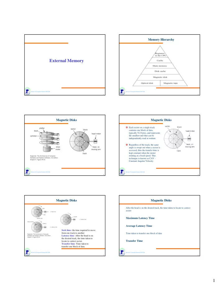
Memory Hierarchy
School of Computer Science G51CSA 3
Magnetic Disks
School of Computer Science G51CSA 4
Magnetic Disks
✪ Each sector on a single track contains one block of data, typically 512 bytes, and represents the smallest unit that can be independently read or written. ✪ Regardless of the track, the same angle is swept out when a sector is accessed, thus the transfer time is kept constant when the motor rotating at a fixed speed. This technique is known as CAV - Constant Angular Velocity.
School of Computer Science G51CSA 5
Magnetic Disks
Seek time: the time required to move from one track to another Latency time: After the head is on the desired track, the time taken to locate to correct sector. Transfer time: Time taken to transfer one block of data.
School of Computer Science G51CSA 6
Magnetic Disks
After the head is on the desired track, the time taken to locate to correct sector
Maximum Latency Time Average Latency Time
Time taken to transfer one block of data