ex
play

ex Gray Codes = reflected binary codes Karnaugh Maps: find (minimal) - PowerPoint PPT Presentation

But first Recall: sum of products logical sum (OR) of products (AND) 1. Basic combinational building blocks of inputs or their complements (NOT). 2. Logic for arithmetic Construct with: A B C M 1 code detector per 1-valued output


  1. But first… Recall: sum of products logical sum (OR) of products (AND) 1. Basic combinational building blocks of inputs or their complements (NOT). 2. Logic for arithmetic Construct with: A B C M • 1 code detector per 1-valued output row 0 0 0 0 • 1 large OR of all code detector outputs 0 0 1 0 Common combinational circuits: encoders, decoders, multiplexers, 0 1 0 0 adders, Arithmetic Logic Unit Is it minimal? 0 1 1 1 1 0 0 0 1 0 1 1 (printed together, separate sets of slides online) 1 1 0 1 1 1 1 1 ex Gray Codes = reflected binary codes 
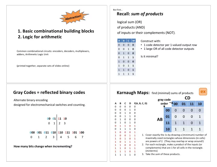
Karnaugh Maps: find (minimal) sums of products CD gray code Alternate binary encoding order 00 01 11 10 A B C D F(A, B, C, D) designed for electromechanical switches and counting. 0 0 0 0 0 00 0 0 0 0 0 0 0 1 0 0 0 1 0 0 01 0 0 0 1 0 0 1 1 0 AB 00 01 11 10 0 1 0 0 0 11 1 1 0 1 0 1 0 1 0 0 1 2 3 0 1 1 0 1 10 1 1 1 1 0 1 1 1 0 000 001 011 010 110 111 101 100 1 0 0 0 1 1. Cover exactly the 1s by drawing a (minimum) number of 1 0 0 1 1 0 1 2 3 4 5 6 7 maximally sized rectangles whose dimensions (in cells) 1 0 1 0 1 are powers of 2. (They may overlap or wrap around!) 1 0 1 1 1 2. For each rectangle, make a product of the inputs (or 1 1 0 0 1 How many bits change when incrementing? complements) that are 1 for all cells in the rectangle. 1 1 0 1 1 ( minterms ) 1 1 1 0 1 3. Take the sum of these products. 1 1 1 1 0

  2. ex Voting again with Karnaugh Maps Toolbox: Building Blocks Processor datapath Microarchitecture Instruction Decoder Memory Arithmetic Logic Unit A B C M Adders Registers 0 0 0 0 Multiplexers 0 0 1 0 Demultiplexers Digital Logic Flip-Flops 0 1 0 0 Encoders Latches Decoders 0 1 1 1 1 0 0 0 Gates 1 0 1 1 1 1 0 1 Devices (transistors, 1 1 1 1 etc.) ex Multiplexers Decoders Select one of several inputs as output. Decodes input number, asserts corresponding output. n -bit input (an unsigned number) D 0 2 n outputs D 1 Built with code detectors. D 2 8-to-1 2 n data inputs D 3 F 1 data output MUX D 4 D 0 D 5 D 0 B 0 D 1 D 6 B 0 D 1 D 7 D 2 B 1 D 2 B 1 D 3 D 3 A B C n selector lines

  3. ex Build a 2-to-1 MUX from gates 8-to-1 MUX If S=0, then F=D 0 . D 0 2-to-1 If S=1, then F=D 1 . F MUX D 1 1. Construct the truth table. S 2. Build the circuit. Costume idea: MUX OX MUX + voltage source = truth table Buses and Logic Arrays A bus is a collection of data lines A B C M treated as a single logical signal. 0 0 0 0 0 = fixed-width value 0 0 1 0 1 0 1 0 0 2 Array of logic elements applies 8-to-1 0 1 1 1 3 same operation to each bit in a bus. M MUX 1 0 0 0 4 = bitwise operator 1 0 1 1 5 1 1 0 1 6 1 1 1 1 7 A B C

  4. Addition: Carry in ex ex 1-bit full adder A start small with a 1-bit (half) adder + Sum B Carry out n-bit addition: Sum i = A i + B i + CarryOut i-1 Need a bigger adder! A B Carry in Carry out Sum Carry in 0 0 0 A B Carry out Sum 0 0 1 A A 0 0 0 1 0 Sum Sum 0 1 0 1 1 B B 1 0 1 0 0 1 1 1 0 1 Carry out Carry out 1 1 0 1 1 1 n-bit ripple-carry adder Carry in Processor Components A 0 + Sum 0 B 0 A 1 + Sum 1 4 1 3 2 B 1 A 2 + Instruction Sum 2 ALU Registers Memory Fetch and B 2 Decode … A n-1 + Sum n-1 B n-1 Carry out There are faster, more complicated ways too…

  5. 1 ex Arithmetic Logic Unit (ALU) 1-bit ALU for bitwise operations Build an n-bit ALU from n 1-bit ALUs. Each bit i in the result is computed from the corresponding bit i in the two inputs. a few bits Condition Codes Op A B Result (sign, overflow, carry-out, zero) 0 0 0 Operation word Operand A 0 0 1 ALU words A Result 0 1 0 0 Operand B MUX 0 1 1 Result 1 0 0 B 1 Operation 1 0 1 a few bits 1 1 0 Hardware unit for arithmetic and bitwise operations. 1 1 1 Carry in 2 Operation 1-bit ALU A 0 n-bit ripple carry adder 0 Result 0 MUX 1 Carry in Sum + B 0 2 A 0 + Operation Sum 0 A 1 B 0 Carry in 2 0 Result 1 MUX A A 1 1 + 0 Sum 1 Sum + B 1 2 B 1 MUX Result A 2 + .... n-bit ALU 1 … Sum 2 B 2 Sum … + A n-1 2 0 B Result n-1 MUX A n-1 + 1 Sum n-1 Sum + B n-1 B n-1 2 Carry out Carry out Carry out

  6. Operation Carry in 2 ALU conditions Operation 2 A 0 0 Add subtraction A 0 Result 0 MUX 0 1 Result 0 Extra ALU outputs MUX + Sum B 0 2 1 describing properties of result. How can we control ALU inputs B 0 + 0 2 or add minimal new logic A 1 Zero Flag: 1 0 to compute A-B ? Result 1 MUX 1 if result is 00...0 else 0 1 A 1 Sum + 0 Sign Flag: B 1 2 Result 1 MUX 1 if result is negative else 0 1 .... … B 1 + Carry Flag: 0 2 1 1 if carry out else 0 .... .... … (Signed) Overflow Flag: A n-1 0 Result n-1 1 if signed overflow else 0 MUX 1 A n-1 Sum + 0 B n-1 2 Result n-1 MUX Implement these. Carry out 1 + B n-1 0 2 1 Carry out Negate B Operation Invert A A NAND B 2 A 0 0 Controlling the ALU 0 1 Result 0 MUX 1 A NOR B B 0 + 0 2 1 Condition Codes ALU control lines Function A 1 0 0 1 0000 AND A<B Result 1 Operand A MUX 1 0001 OR ALU + Result B 1 0 2 0010 add 1 Operand B A==B 0110 subtract .... .... .... … 1100 NOR Control Lines A n-1 0 0 1 Result n-1 MUX How can we control ALU inputs 1 or add minimal new logic B n-1 + 0 ex to compute each? 2 1 Carry out

Download Presentation
Download Policy: The content available on the website is offered to you 'AS IS' for your personal information and use only. It cannot be commercialized, licensed, or distributed on other websites without prior consent from the author. To download a presentation, simply click this link. If you encounter any difficulties during the download process, it's possible that the publisher has removed the file from their server.

Recommend


More recommend