electric circuit components
play

Electric circuit components Capacitor stores charge and potential - PDF document

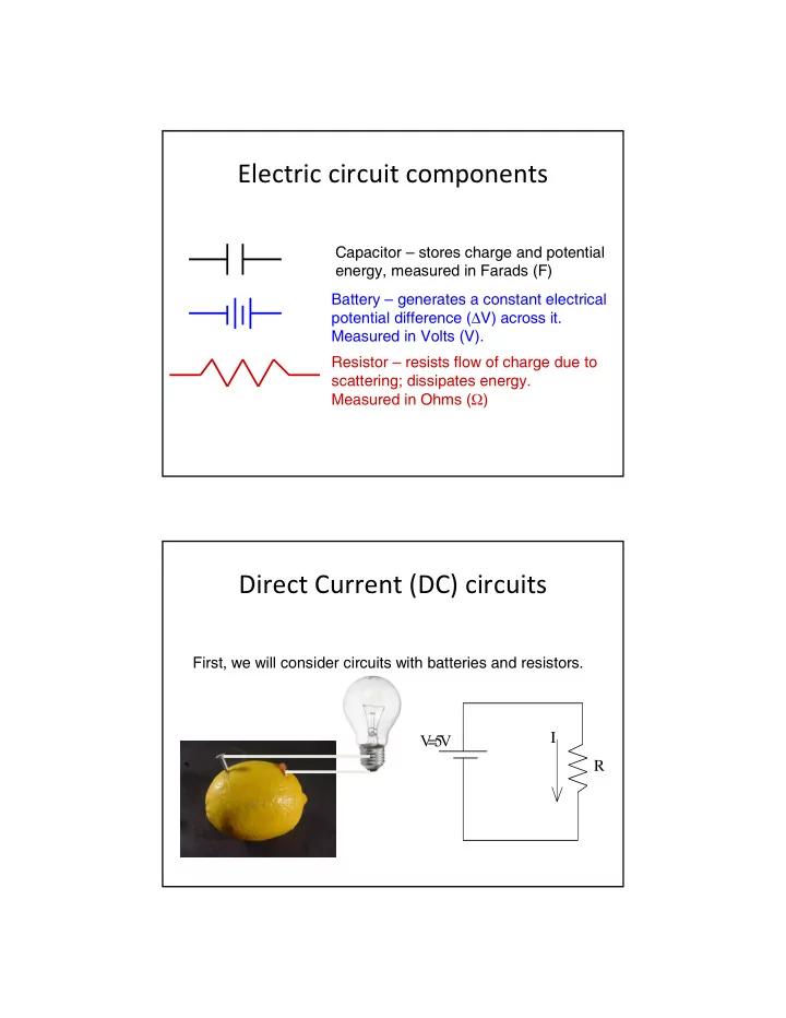
Electric circuit components Capacitor stores charge and potential energy, measured in Farads (F) Battery generates a constant electrical potential difference ( V) across it. Measured in Volts (V). Resistor resists flow of charge


  1. Electric circuit components Capacitor – stores charge and potential energy, measured in Farads (F) Battery – generates a constant electrical potential difference ( ∆ V) across it. Measured in Volts (V). Resistor – resists flow of charge due to scattering; dissipates energy. Measured in Ohms ( Ω ) Direct Current (DC) circuits First, we will consider circuits with batteries and resistors. I V = 5 V R

  2. Resistors in Series The current through all = = = I I I I 1 2 3 resistors is the same = = V V IR 1 ax 1 = = V V IR ( ) = + + = + + V ab V V V I R R R 2 xy 2 1 2 3 1 2 3 = = V V IR 3 yb 3 = → = + + V IR R R R R ab eq eq 1 2 3 Resistors in Series = R R ∑ eq i i Adding resistors in series always increases the total resistance.

  3. Resistors in Series: Example Calculate I and V across each resistor I bat I A R A R A = 1.0 Ω V V = 6 Volts I B R B = 3.0 Ω R B Clicker Question Two different wires are connected to a battery in series (in a chain, one after another). How does the current in upper wire A compare to the current in lower wire B? I bat I A R A A) i A > i B V B) i A < i B I B C) i A = i B R B D) Impossible to determine.

  4. Resistors in Series: Example What is the equivalent resistance? I bat I A R A = + = Ω + Ω = Ω R eq R R 1 . 0 3 . 0 4 . 0 V 1 2 What is the current through the circuit? I B R B Assuming everything is Ohmic, V=IR V 6 V = = = = = i i i 1 . 5 A A B Ω R 4 . 0 eq Resistors in Series: Example What about the Voltage change across each resistor? I bat I A R A R A = 1.0 Ω, i A A =1.5 A =1.5 A V V = 6 Volts I B R B = 3.0 Ω, i B = 1.5 A R B = ∆ = = Ω = V V i R ( 1 . 5 A )( 1 . 0 ) 1 . 5 V A A A A = ∆ = = Ω = V V i R ( 1 . 5 A )( 3 . 0 ) 4 . 5 V B B B B

  5. Clicker Question If we consider the Voltage change starting at Point P and going all the way around the I bat I A R A circuit loop back to Point P, what is the total V ∆ V? Α)∆ V = +6.0 Volts I B Β)∆ V = +1.5 Volts R B C) ∆ V = -4.5 Volts D) ∆ V = 0.0 Volts Point P E) ∆ V = -6.0 Volts Resistors in Series: Example Voltage P2 P3 6V I bat I A R A 4.5V V P4 3.0V I B R B 1.5V P1 P5 0.0V Position 1 2 3 4 5 1 In Loop Define V=0 at P1.

  6. Clicker Question We start with the left circuit with one lightbulb (A). The brightness of the bulb directly reflects the power. If we add a second bulb (B) as shown on the right, what happens to the bulbs? A)Bulb A is equally bright. B)Bulb A is dimmer than before V V A A B C)Bulb A is brighter than before Clicker Question Two light bulbs, A and B, are in series, so they carry the same current. Light bulb A is brighter than B. Which bulb has higher resistance? A) A B) B C) Same resistance. Answer: Bulb A has higher resistance. Since the resistors are in series, they have the same current I. According to V P = I 2 R, if I = constant, then higher R A B gives higher P.

  7. Clicker Question If we connect a battery with V = 6 Volts with three resistors R1 = 10 Ω , R2 = 20 Ω , R3 = 30 Ω , which of the following is true? A)The current through each resistor is the same. B)The Voltage change through each resistor is the same. C)The resistance of each resistor is the same. D)None of the above are true. Resistors in Parallel The voltage across all = = = ab = V V V V V 1 2 3 resistors is the same = I V / R 1 1 ⎛ ⎞ 1 1 1 = = + + = ⎜ + + ⎟ I V / R I I I I V ⎜ ⎟ 1 2 3 2 2 R R R ⎝ ⎠ 1 2 3 = I V / R 3 3 = → = + + I V / R 1 1 1 1 eq R R R R eq 1 2 3

  8. Resistors in Parallel 1 1 = ∑ R R i eq i Adding resistors in parallel always decreases the total resistance. Traffic analog Resistors in parallel are like having more lanes on the highway. This reduces the resistance for getting from one place to another.

  9. Resistors in parallel: Example = + + I I I I i 1 i 2 R 1 1 2 3 R 2 R 3 i i 3 If all three resistors were the same then: V 1 = = = I I I I 1 2 3 3 Resistor configurations Resistors in Series Resistors in Parallel 1 = R eq = + + R eq R R R 1 1 1 1 2 3 + + R R R 1 2 3 Always decreases the resistance! Always increases the resistance!

  10. Clicker Question We start with the left circuit with one lightbulb (A). The brightness of the bulb directly reflects the power. If we add a second identical bulb (B) as shown on the right, what happens to the bulbs? B A)Bulb A is equally bright. A B)Bulb A is dimmer A than before C)Bulb A is brighter than before V=12V V=12V Clicker Question If each of these six light bulbs is identical, which bulb is going to be the brightest? A)Bulb A B)Bulb B C)Bulb C D)Bulb D E)Bulb E

  11. Clicker Question The three light bulbs A, B, and C are identical. How does the brightness of bulbs B and C together compare with the brightness of bulb A? A) Total power in B+C = power in A. A B) Total power in B+C > power in A. C) Total power in B+C < power in A. B C Answer: Use P = V 2 /R tot For bulbs B and C, R tot = 2R. V=12V Total power in B+C < power in A. Clicker Question In the circuit below, what happens to the brightness of bulb 1, when bulb 2 burns out? (When a bulb burns out, its resistance becomes infinite.) 2 A) Bulb 1 gets brighter B) Bulb 1 gets dimmer. C) It's brightness remains the same. 3 (Hint: What happens to the current from 1 the battery when bulb 2 burns out.) V=12V

  12. Answers: Bulb 1 gets dimmer! When bulb 2 burns outs, the filament inside breaks and R2 becomes infinitely large. The total equivalent resistance which the battery sees increases (since bulb 2 is gone, there are fewer paths for the current flow, so less flow, more total resistance.) Since the battery sees a larger R-tot, the current from the battery I-tot = V/Rtot is reduced. Less current from the battery means less current through bulb 1, less light. 2 3 1 V=12V CPS question Which is the best way to wire a house? (A) (B)

  13. Resistor networks Resistor networks

  14. Kirchhoff’s rules Kirchhoff’s Voltage Loop Law: The change in Voltage around any closed loop must be zero. Kirchhoff’s Current Junction Law: In steady state, the current going into a junction (or point) must equal the current going out of that junction (or point). Clicker Question What is the electric potential difference across the upper light bulb (resistor)? Think about our Voltage Loop Rule. A)|V| = 0 Volts B)|V| = 6 Volts C)|V| = 12 Volts D)|V| = 24 Volts E)None of the above answers. V=12V

  15. Kirchhoff’s rules: Example Example 1: Choose R1 = R2 = R3 = 10 Ω 1. Longer line on battery is i 2 2 higher voltage and the shorter line is lower voltage, i 1 i 3 by convention. 2. We label the current in 3 1 each section as shown. i b i b Note that we can guess the i b direction at this point. The - + answer will be independent V=12V of our guess. i b Kirchhoff’s rules: Example 3. Apply the Voltage Loop Rule around each possible i 2 2 loop in the circuit. Make sure to label the i 1 i 3 direction of your loop! 3 Make sure to pick a starting 1 i b point to go around the loop. i b i b Then add up the Voltage - + changes around the loop. V=12V i b

  16. Critical Sign Convention! Critical Sign Convention! - + If your loop goes through a battery from – to + V=12V the Voltage increases (e.g. ∆ V = +12 V) - + If your loop goes through a battery from + to – V=12V the Voltage decreases (e.g. ∆ V = -12 V) Critical Sign Convention! Critical Sign Convention! i If you go across a resistor and the loop 2 direction and guessed current direction are the same, the voltage decreases (e.g. ∆ V = -iR) i If you go across a resistor and the loop 2 direction and guessed current direction are opposite, the voltage increases (e.g. ∆ V = +iR)

  17. Kirchhoff’s rules: Example Starting at Point P go around the loop. i 2 2 ∆ = + V bat 12 V ∆ = − V R i R i 1 i 3 3 3 3 ∆ = − V R i R 3 1 1 1 1 ∆ = + − − = i b V sum 12 i R i R 0 i b 3 3 1 1 i b - + P V=12V i b Kirchhoff’s rules: Example Now try other path starting at Point P around the new loop. i 2 2 ∆ = + V bat 12 V ∆ = − V R i R i 1 i 3 2 2 2 ∆ = − V R i R 3 1 1 1 1 ∆ = + − − = V sum 12 i R i R 0 i b 2 2 1 1 i b - + P V=12V i b

  18. Kirchhoff’s rules: Example For our specific circuit, we used R1 = R2 = R3 = 10 Ω ∆ = + − − = − − = V sum 12 i R i R 0 12 10 i 10 i 0 3 3 1 1 3 1 ∆ = + − − = − − = V sum 12 i R i R 0 12 10 i 10 i 0 2 2 1 1 2 1 We have two equations and three unknowns. We need additional information. Kirchhoff’s rules: Example Apply the current junction rule at point Q below. = i i i 2 2 in out + = i i i i 1 i 3 2 3 1 Q 3 1 Also, (as we could have i b i b done at the start): i b i = i - + 1 b V=12V i b

Download Presentation
Download Policy: The content available on the website is offered to you 'AS IS' for your personal information and use only. It cannot be commercialized, licensed, or distributed on other websites without prior consent from the author. To download a presentation, simply click this link. If you encounter any difficulties during the download process, it's possible that the publisher has removed the file from their server.

Recommend


More recommend