
SLIDE 1
EELE 354: Electric Power Applications
Lecture 6: Resistive Electrical Circuits Practice
09/16/2013
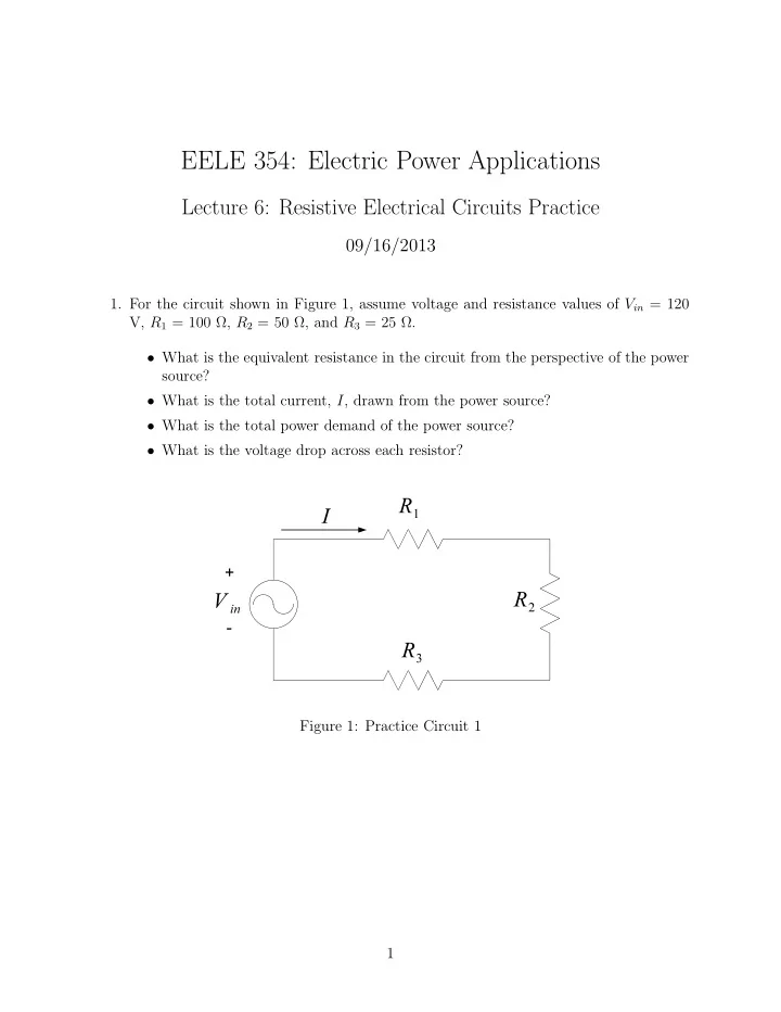
- 1. For the circuit shown in Figure 1, assume voltage and resistance values of Vin = 120
V, R1 = 100 Ω, R2 = 50 Ω, and R3 = 25 Ω.
- What is the equivalent resistance in the circuit from the perspective of the power
source?
- What is the total current, I, drawn from the power source?
- What is the total power demand of the power source?
- What is the voltage drop across each resistor?