
SLIDE 1
1
EECS 373
Design of Microprocessor-Based Systems
Prabal Dutta
University of Michigan Lecture 10: Serial buses October 2, 2014
Some material from: Brehob, Le, Ramadas, Tikhonov & Mahal
EECS 373 Design of Microprocessor-Based Systems Prabal Dutta - - PowerPoint PPT Presentation
EECS 373 Design of Microprocessor-Based Systems Prabal Dutta University of Michigan Lecture 10: Serial buses October 2, 2014 Some material from: Brehob, Le, Ramadas, Tikhonov & Mahal 1 Announcements Special Topics groups Fill out
1
Some material from: Brehob, Le, Ramadas, Tikhonov & Mahal
– Fill out Google Sheets by 10/7 (sooner is better – tiebreaker)
– Will send out link to class email list
– Contact me by 10/3 if you have a conflict or concern
2
3
– In the general case, a bus may have more than one device capable of driving it.
earlier.
– Pros:
efficient. – Cons:
– Especially drive-to-tristate?
– Let out the magic smoke. – Most common solution (at least historically)
– Just have each device generate its data, and have a MUX select.
– Consider a 32-bit bus with 6 potential drivers. » Draw the figure. » How many pins needed for the MUX? – Not generally realistic for an “on-PCB” design as we’ll need an extra device (or a lot of pins on one device)
– In fact AHB, APB do this.
collector” aka “wired AND”
– Wire is pulled high by a resistor – If any device pulls the wire low, it goes low.
– If two devices both drive the bus, it still works!
– Rise-time is very slow. – Constant power drain.
– If two devices both drive the bus, it still works!
– Rise-time is very slow. – Constant power drain.
8 Atmel SAM3U
9
10
Most of the UART stuff (including images) Taken from Wikipedia!
– a logic low start bit – a configurable number of data bits (usually 7 or 8, sometimes 5) – an optional parity bit – one or more logic high stop bits – with a particular bit timing (“baud”)
– “9600-N-8-1” ! <baudrate><parity><databits><stopbits> – “9600-8-N-1” ! <baudrate><databits><parity><stopbits>
11
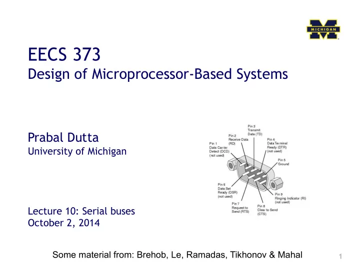
– RS-232 is a standard that specifies
meaning of signals, and the physical size and pin
12
be an input and is usually connected to the TXD line of the downstream device.
will be an output and is usually connected to the RXD line of the downstream device.
the downstream device that the device is ready to receive data. This will be an output and is usually connected to the CTS# line of the downstream device.
downstream device to identify that it is OK to transmit data to the upsteam device. This will be an input and is usually connected to the RTS# line of the upstream device.
13
14
Wiring a DTE device to a DCE device for communication is easy. The pins are a one-to-one connection, meaning all wires go from pin x to pin x. A straight through cable is commonly used for this application. In contrast, wiring two DTE devices together requires crossing the transmit and receive wires. This cable is known as a null modem or crossover cable.
15
– 9600-8-N-1 is ok. Is 9600-8192-N-1 ok too?
16
17
" What is it? " Basic Serial Peripheral Interface (SPI) " Capabilities " Protocol " Pro / Cons and Competitor " Uses " Conclusion
Serial Peripheral Interface
http://upload.wikimedia.org/wikipedia/commons/thumb/e/ed/ SPI_single_slave.svg/350px-SPI_single_slave.svg.png
" A communication protocol using 4 wires
" Also known as a 4 wire bus
" Used to communicate across small
" Multiple Slaves, Single Master " Synchronized
" Always Full Duplex
" Communicating in two directions at the
" Transmission need not be meaningful
" Multiple Mbps transmission speed " Transfers data in 4 to 16 bit characters " Multiple slaves
" Daisy-chaining possible
" Wires:
" Master Out Slave In (MOSI) " Master In Slave Out (MISO) " System Clock (SCLK) " Slave Select 1…N
" Master Set Slave Select low " Master Generates Clock " Shift registers shift in and out data
" MOSI – Carries data out of Master to
" MISO – Carries data from Slave to
" Both signals happen for every transmission
" SS_BAR – Unique line to select a slave " SCLK – Master produced clock to
Master shifts out data to Slave, and shift in data from Slave
http://upload.wikimedia.org/wikipedia/commons/thumb/b/bb/SPI_8-bit_circular_transfer.svg/400px-SPI_8-bit_circular_transfer.svg.png
Master and multiple independent slaves
http://upload.wikimedia.org/wikipedia/commons/thumb/f/fc/ SPI_three_slaves.svg/350px-SPI_three_slaves.svg.png
Master and multiple daisy- chained slaves
http://www.maxim-ic.com/appnotes.cfm/an_pk/3947
Some wires have been renamed
" Two phases and two polarities of clock " Four modes " Master and selected slave must be in
" Master must change polarity and phase
Timing Diagram – Showing Clock polarities and phases
http://www.maxim-ic.com.cn/images/appnotes/3078/3078Fig02.gif
" Fast and easy
" Fast for point-to-point connections " Easily allows streaming/Constant data inflow " No addressing/Simple to implement
" Everyone supports it
" SS makes multiple slaves very complicated " No acknowledgement ability " No inherent arbitration " No flow control
" Some Serial Encoders/Decoders,
" Pre-SPI serial devices
" SPI – 4 wire serial bus protocol
" MOSI MISO SS SCLK wires
" Full duplex " Multiple slaves, One master " Best for point-to-point streaming data " Easily Supported
31
33
34
35
36
37
38
39
40
41
42
43
44
– 0’s are driven – 1’s are “pulled up”
– Rp = 10 kΩ – Ccap = 100 pF – VDD = 5 V – Vin_high = 3.5 V
– Vcap(t) = VDD(1-e-t/τ) – Where τ = RC
45
– <S><A6:A0><R/W><A><D7:D0><A><F>
– <S><A6:A0><R/W><A><D7:D0><A><F>
– What is the clock period? – What is the data throughput (i.e. data-bits/second)? – What is the bus “efficiency”?