
SLIDE 1
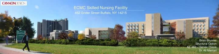
ECMC Skilled Nursing Facility
462 Grider Street Buffalo, NY 14215
Brian Brunnet Structural Option AE 482 – Senior Thesis
- Dr. Ali Memari
ECMC Skilled Nursing Facility 462 Grider Street Buffalo, NY 14215 - - PowerPoint PPT Presentation
ECMC Skilled Nursing Facility 462 Grider Street Buffalo, NY 14215 Brian Brunnet Structural Option AE 482 Senior Thesis Dr. Ali Memari Presentation Outline 1. Project Background 2. Scope of Work 3. Structural Depth Study i.
1. Project Background 2. Scope of Work 3. Structural Depth Study i. Foundation System ii. Gravity System iii. Lateral Force Resisting System 4. Mechanical Breadth 5. Construction Management Breadth 6. Summary of Conclusions 7. Acknowledgments
Building Statistics:
Project Team:
1. Project Background 2. Scope of Work 3. Structural Depth Study i. Foundation System ii. Gravity System iii. Lateral Force Resisting System 4. Mechanical Breadth 5. Construction Management Breadth 6. Summary of Conclusions 7. Acknowledgments
Existing Structural System Foundation System:
1. Project Background 2. Scope of Work 3. Structural Depth Study i. Foundation System ii. Gravity System iii. Lateral Force Resisting System 4. Mechanical Breadth 5. Construction Management Breadth 6. Summary of Conclusions 7. Acknowledgments
Existing Structural System Gravity System:
Decking
1. Project Background 2. Scope of Work 3. Structural Depth Study i. Foundation System ii. Gravity System iii. Lateral Force Resisting System 4. Mechanical Breadth 5. Construction Management Breadth 6. Summary of Conclusions 7. Acknowledgments
Existing Structural System Lateral Force Resisting System:
7x7x1/2
surrounding the building core
Problem Statement:
and economical
Angeles, CA
Problem Solution:
Buffalo, NY Los Angeles, CA
1. Project Background 2. Scope of Work 3. Structural Depth Study i. Foundation System ii. Gravity System iii. Lateral Force Resisting System 4. Mechanical Breadth 5. Construction Management Breadth 6. Summary of Conclusions 7. Acknowledgments
Project Goals: Structural Depth Study
Systems for new location Mechanical Breadth Study
for new location’s climate Construction management Breadth Study
1. Project Background 2. Scope of Work 3. Structural Depth Study i. Foundation System ii. Gravity System iii. Lateral Force Resisting System 4. Mechanical Breadth 5. Construction Management Breadth 6. Summary of Conclusions 7. Acknowledgments Buffalo, NY:
Los Angeles, CA:
The following systems will be evaluated: Foundation System Gravity System Lateral Force Resisting System
1. Project Background 2. Scope of Work 3. Structural Depth Study i. Foundation System ii. Gravity System iii. Lateral Force Resisting System 4. Mechanical Breadth 5. Construction Management Breadth 6. Summary of Conclusions 7. Acknowledgments
Los Angeles, CA:
Solution: Deep Foundation
1. Project Background 2. Scope of Work 3. Structural Depth Study i. Foundation System ii. Gravity System iii. Lateral Force Resisting System 4. Mechanical Breadth 5. Construction Management Breadth 6. Summary of Conclusions 7. Acknowledgments
Deep Foundation Design Results:
1. Project Background 2. Scope of Work 3. Structural Depth Study i. Foundation System ii. Gravity System iii. Lateral Force Resisting System 4. Mechanical Breadth 5. Construction Management Breadth 6. Summary of Conclusions 7. Acknowledgments
Framing Plan:
1. Project Background 2. Scope of Work 3. Structural Depth Study i. Foundation System ii. Gravity System iii. Lateral Force Resisting System 4. Mechanical Breadth 5. Construction Management Breadth 6. Summary of Conclusions 7. Acknowledgments
Design Loads:
Serviceability Criteria: Deflection
Controlling Load Combination:
1. Project Background 2. Scope of Work 3. Structural Depth Study i. Foundation System ii. Gravity System iii. Lateral Force Resisting System 4. Mechanical Breadth 5. Construction Management Breadth 6. Summary of Conclusions 7. Acknowledgments
Gravity System Design Results:
1. Project Background 2. Scope of Work 3. Structural Depth Study i. Foundation System ii. Gravity System iii. Lateral Force Resisting System 4. Mechanical Breadth 5. Construction Management Breadth 6. Summary of Conclusions 7. Acknowledgments
Lead-Core Rubber Base Isolation:
Member Size W14x370 W14x283 Displacement (@ 90') 2.971" 2.64" Drift (@90') 0.025" 0.018" Seismic Base Isolation Comparison (Los Angeles, CA) Building Period 1.4754 sec 4.1803 sec No Base Isolation Base Isolation Base Shear 6550 kips 6550 kips Total Moment 350,694 ft-k 350,694 ft-k
re-aligns building after quake
1. Project Background 2. Scope of Work 3. Structural Depth Study i. Foundation System ii. Gravity System iii. Lateral Force Resisting System 4. Mechanical Breadth 5. Construction Management Breadth 6. Summary of Conclusions 7. Acknowledgments
V Kd n1 Kzt qz qh G Cp External Pressure Coefficient (Leeward) Cp
varies
varies 23.96 0.859
0.8 Exposure Category Kz GCpi Gust Effect Factor 0.85 III B Enclosed 0.18 ASCE Reference Product of Internal Pressure Coefficient and Gust Effect Factor Velocity Pressure Exposure Coefficient evaluated at Height Z External Pressure Coefficient (Windward) 0.833 (flexible) 1 Building Natural Frequency Topographic Factor Velocity Pressure at Height Z Velocity Pressure at Mean Roof Height Wind Variables Basic Wind Speed Directional Factor Occupancy Category Exposure Classification 115mph
Ss S1 Fa Fv Sms Sm1 Sds Sd1 Sdc R hn North/South North/South Ct 0.02 0.02 x 0.75 0.75 Cu 1.4 1.4 Ta 0.584 0.584 T 1.4081 4.1803 TL 8 8 Cs 0.304 0.304 k 1.042 1.042 ASCE Reference Building Height (above grade) (ft) 0.853 1 2.432 Spectral Response Acceleration, 1 s Site Coefficient Site Coefficient MCE Spectral Response Acceleration, short MCE Spectral Response Acceleration, 1 s Design Spectral Acceleration, Short Site Class Occupancy Category Importance Factor Spectral Response Acceleration, short Structural System Steel Special Concentrically Braced Frames Seismic Design Variables
East/West 1.622 Approximate Period Parameter
0.02 0.75
0.02 1.279 1.622 0.853 E 6.0 90 Approximate Period Parameter Design Spectral Acceleration, 1 s Seismic Design Category Calculated Period Upper Limit Coefficient Approximate Fundamental Period Fundamental Period Long Period Transition Period Seismic Response Coefficient Structural Period Exponent Response Modification Coefficient 1.5
8 0.304 1.042
1.4 0.584 1.4754 2.432 0.853 1 1.5 2.432 1.279 No Base Isolation Base Isolated D III 1.25 Steel Special Concentrically Braced Frames D III 1.25 2.432 1.4 0.584 4.1866 8 0.304 1.042 0.853 E 6.0 90 East/West 0.75
Wind Design Variables Seismic Design Variables
1. Project Background 2. Scope of Work 3. Structural Depth Study i. Foundation System ii. Gravity System iii. Lateral Force Resisting System 4. Mechanical Breadth 5. Construction Management Breadth 6. Summary of Conclusions 7. Acknowledgments
Design Loads:
Serviceability Criteria: Drift Criteria
Controlling Load Combination:
1. Project Background 2. Scope of Work 3. Structural Depth Study i. Foundation System ii. Gravity System iii. Lateral Force Resisting System 4. Mechanical Breadth 5. Construction Management Breadth 6. Summary of Conclusions 7. Acknowledgments
Relative Story Stiffness: X Direction
Frame # A1 A8 B9 B15 C1 C8 D9 D15
4.127 4.173
3.147 3.130 3.104 3.117 3.100 3.117 3.144 3.130 4 2.147 2.126 2.093 2.110 2.089 2.110 2.144 2.126 3 1.317 1.296 1.264 1.280 1.260 1.280 1.313 1.296 2 0.665 0.652 0.632 0.642 0.629 0.642 0.663 0.652 1 0.263 0.257 0.246 0.252 0.245 0.252 0.262 0.257 Frame # A1 A8 B9 B15 C1 C8 D9 D15 ΣKix
242.3068 239.6358
317.7848 319.4888 322.2065 320.8316 322.5494 320.7801 318.056 319.4786 2561.176 4 465.812 470.4775 477.7374 474.001 478.675 473.8663 466.5267 470.3226 3777.419 3 759.5806 771.9027 791.4523 781.3721 793.9659 781.0059 761.4406 771.5454 6212.266 2 1504.352 1534.684 1583.03 1558.118 1589.572 1557.147 1508.978 1533.742 12369.62 1 3796.522 3897.116 4060.089 3974.563 4081.633 3972.984 3812.429 3894.081 31489.42 Σkix,total : 56891.84 Frame # A1 A8 B9 B15 C1 C8 D9 D15
0.502771 0.497229
0.124078 0.124743 0.125804 0.125267 0.125938 0.125247 0.124184 0.124739 4 0.123315 0.12455 0.126472 0.125483 0.12672 0.125447 0.123504 0.124509 3 0.122271 0.124255 0.127402 0.125779 0.127806 0.12572 0.122571 0.124197 2 0.121617 0.124069 0.127977 0.125963 0.128506 0.125885 0.121991 0.123993 1 0.120565 0.12376 0.128935 0.126219 0.129619 0.126169 0.12107 0.123663 0.122369 0.124275 0.127318 0.125742 0.127718 0.125694 0.122664 0.12422 P = 1000 kips Relative Story Stiffness Ratio (Rix) X-Direction Displacement Δp (in) Story Stiffness Kix = P/Δp (kip/in) Relative Story Stiffness Ratio Rix = Kix/Kix,total Average
Frame Stiffness:
contribution
1. Project Background 2. Scope of Work 3. Structural Depth Study i. Foundation System ii. Gravity System iii. Lateral Force Resisting System 4. Mechanical Breadth 5. Construction Management Breadth 6. Summary of Conclusions 7. Acknowledgments
1. Project Background 2. Scope of Work 3. Structural Depth Study i. Foundation System ii. Gravity System iii. Lateral Force Resisting System 4. Mechanical Breadth 5. Construction Management Breadth 6. Summary of Conclusions 7. Acknowledgments
Mechanical System:
Buffalo, NY:
Los Angeles, CA:
1. Project Background 2. Scope of Work 3. Structural Depth Study i. Foundation System ii. Gravity System iii. Lateral Force Resisting System 4. Mechanical Breadth 5. Construction Management Breadth 6. Summary of Conclusions 7. Acknowledgments
Mechanical System Results: Buffalo, NY:
season Los Angeles, CA:
1. Project Background 2. Scope of Work 3. Structural Depth Study i. Foundation System ii. Gravity System iii. Lateral Force Resisting System 4. Mechanical Breadth 5. Construction Management Breadth 6. Summary of Conclusions 7. Acknowledgments
Cost Analysis:
1. Project Background 2. Scope of Work 3. Structural Depth Study i. Foundation System ii. Gravity System iii. Lateral Force Resisting System 4. Mechanical Breadth 5. Construction Management Breadth 6. Summary of Conclusions 7. Acknowledgments
Schedule Impact:
1. Project Background 2. Scope of Work 3. Structural Depth Study i. Foundation System ii. Gravity System iii. Lateral Force Resisting System 4. Mechanical Breadth 5. Construction Management Breadth 6. Summary of Conclusions 7. Acknowledgments
Foundation Redesign:
Gravity System Redesign:
requirements
Lateral System Redesign:
seismic
Mechanical Breadth:
Construction Management Breadth:
1. Project Background 2. Scope of Work 3. Structural Depth Study i. Foundation System ii. Gravity System iii. Lateral Force Resisting System 4. Mechanical Breadth 5. Construction Management Breadth 6. Summary of Conclusions 7. Acknowledgments
Cannon Design:
The Pennsylvania State University:
All my friends, family, and classmates for their continuous support and encouragement
1. Project Background 2. Scope of Work 3. Structural Depth Study i. Foundation System ii. Gravity System iii. Lateral Force Resisting System 4. Mechanical Breadth 5. Construction Management Breadth 6. Summary of Conclusions 7. Acknowledgments