
SLIDE 1
DUNE Far Detector
Anode Panel, Cathode Panel, and Field Cage Installation
- V. Guarino & R. Kmak
DUNE Far Detector Anode Panel, Cathode Panel, and Field Cage - - PowerPoint PPT Presentation
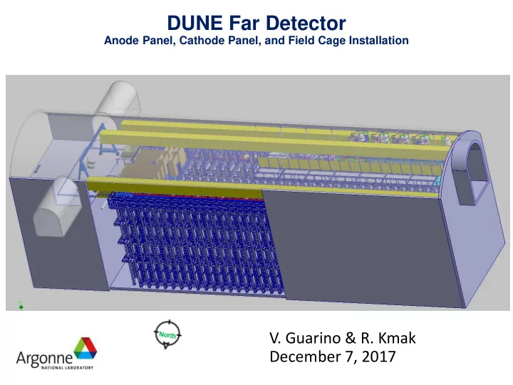
DUNE Far Detector Anode Panel, Cathode Panel, and Field Cage Installation V. Guarino & R. Kmak December 7, 2017 DUNE Installation Define Requirements for Underground Installation Define detector components and identify space
Anode Panel, Cathode Panel, and Field Cage Installation
2
3
Components will be moved into the Clean Room in sufficient quantities to assemble & install ‘one set’
4
5
Anode Panel Assembly (APA) ~12 m tall Cathode Panel Assembly (CPA) ~12 m tall Field Cage (FC) Upper Assembly Area a.k.a. ‘Pedestal’ Lower Assembly Area a.k.a. ‘Toaster’ Some features and / or components may or may not be shown on subsequent slides for clarity. Clean Room Boundary Cryostat Access Door Gantry Crane Footbridge Person Person Clean Room Boundary
6
7
DUNE Far Detector
Assembly Area / Clean Room Boundaries
Plan View - All Dimensions are Estimated
8
DUNE Far Detector
Assembly Area / Clean Room Boundaries
Elevation View, Looking East to West. All Dimensions are Estimated
9
10
Assumed APA and FCA Crate Sizes and Capacity
APA – one complete panel per shipping container, shipped in ~6m sections CPA – one complete panel per shipping container, shipped in ~4m sections Middle Upper 1/3 panel Lower 1/3 panel Upper 1/3 panel Crate covers not shown
11
Assumed FC Crate Size and Capacity
FC – two complete panels per shipping container Upper panels packaged ‘hinges UP’ Lower panels shipped ‘hinges DOWN’. FC Crate has an inner structure to support the FC. Top and sides removed tor loading & unloading of FCs Loaded Crate (top not shown)
12
DUNE Far Detector
Panel Components Staged in Clean Room
13
14
1) Half (~6m) of APA removed from crate 4) Lowered into Assembly fixture 3) Rotated to align with assembly fixture 2) Rotated to stand vertically
APA crates are not designed so assuming vertical lift out of crate
15
1 - Boxed CPA in
being raised from crate 2 - CPA panel being lowered into Toaster 3 - CPA panels (6 x 1/3) Assembled at bottom of Toaster
16
FC Panel FC Removed from crate, being lowered into Toaster
17
FC Panel FC Panels are assembled to FC array inside Toaster CPA Panel
18
19
DUNE Far Detector
APA assembly & Fixture Location – Option ‘A’
Cryostat Structure TCO Bridge Lift platform 2m sq APA Fixture APA Panel Toaster Wall Gantry
20
DUNE Far Detector
APA assembly & Fixture Location – Option ‘B’
Cryostat Structure TCO Bridge Lift platform 2m sq APA Fixture APA Panel Toaster Wall Gantry
21
DUNE Far Detector
APA assembly & Fixture Location – Option ‘C’
Cryostat Structure TCO Bridge Fixed Platform Elevated 8 ft apart (4) at Each work station APA Fixture APA Panel Toaster Wall Gantry
Cryo Towers removed providing greater space – access scaffolding
22
DUNE Far Detector
APA assembly & Fixture Location – Option ‘D’
Cryostat Structure TCO Bridge Fixed Platform Elevated 8 ft apart (4) at Each work station APA Fixture APA Panel Toaster Wall Gantry Movable Man-Lift Movable Man-Lift Foot Bridge Toaster Wall
Cryo Towers removed providing greater space – access scaffolding and lift
23
DUNE Far Detector
APA / CPA Installation into Cryostat
Anode Panel Assembly (APA) Cathode Panel Assembly (CPA)
24
DUNE Far Detector
APA / CPA Installation into Cryostat
DSS System Shuttle System
25
DUNE Far Detector
Completed Panel Transportation
FC Panel Completed Panels are shuttled to their proper row
place inside the Cryostat CPA Panel APA Panel
26
DUNE Far Detector
[slide title here]
Anode Panel Assembly (APA) Cathode Panel Assembly (CPA) Field Cage (FC) Anode Panel Assembly (APA)
North
Remove option install FC to CPA on ped – FC / CPA install will be in toaster New sheets: 1 - In-toaster assembly (several sheets) 2 – alternate position (on ped wall) for APA fixture