DRAFT presentation for DP ProtoDUNE Design Review 24 th April 17 - - PowerPoint PPT Presentation

draft presentation for dp protodune design review 24 th
SMART_READER_LITE
LIVE PREVIEW

DRAFT presentation for DP ProtoDUNE Design Review 24 th April 17 - - PowerPoint PPT Presentation

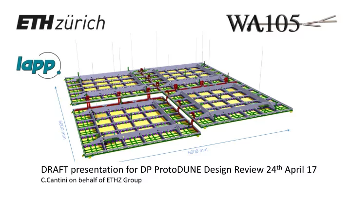
DRAFT presentation for DP ProtoDUNE Design Review 24 th April 17 C.Cantini on behalf of ETHZ Group Instrumentation: from 311 Detector to protoDUNE DP Temperature probes Insulation space Inner vessel Instrumentation flanges,


slide-1
SLIDE 1

DRAFT presentation for DP ProtoDUNE Design Review 24th April 17

C.Cantini on behalf of ETHZ Group

slide-2
SLIDE 2

Instrumentation: from 311 Detector to protoDUNE DP

  • Temperature probes
  • Insulation space
  • Inner vessel
  • Instrumentation flanges, connectors internal cabling
  • Distribution of sensors on Charge Readout Plane
  • Patch panel
  • Calibration system
  • Level meter system
  • Middle HV system

2

DP protoDUNE instrumentation/slow control design is profiting a lot from commissioning of 311 Detector. Continued prototyping efforts toward multi Kton Det.

C.Cantini, WA105 GM

slide-3
SLIDE 3

Based on new sensors list and previous experience with 311 Detector, preliminary design for Flanges hosting CRP INS. 4 x CRP INS flange dedicated to:

  • Slow control signals (temperatures, LAr level

meters, pressure…)

  • Connectors as 311 Detector
  • Improving internal cabling
  • Middle High Voltage (10 kV rated channels)
  • Pulsing system: under consideration

Penetrations already defined: 80 mm dia, CF250 flange for CRP INS. A tee or cross will be needed, similarly to TANK INS Flanges CRP Instrumentation Feedthroughs

CRP Instrumentation Feedthroughs

3 C.Cantini, WA105 GM

Signal Feedthroughs

slide-4
SLIDE 4

Distribution of temperature sensors and level meter

4

slide-5
SLIDE 5
  • PCB panel fixed on Charge Readout Plane – each module

has one

  • Purpose of the panel is to ease installation and cabling
  • Temperature sensors distributed on CRP
  • Liquid argon level meter for CRP positioning and

distance meter for relative alignment of modules

  • Pulsing system
  • A second patch panel for LEM biasing – under

development

A patch panel as interface in the vessel for sensors

Cabling in collaboration with Confectronic, Allectra and

  • ther workshops at CERN for custom made assemblies.

5

HV patch panel: design still pending, it depends on HV Flange

C.Cantini, WA105 GM

slide-6
SLIDE 6
  • 311 Detector has o(90) temperature probes distributed in main vessel,

soldered on ribbon cable, spaced by 4 cm or arranged on “thermometers”

  • 311 Detector has 45 temperature probes in the insulation space
  • 4 wires method everywhere
  • Pt interfaced to NI9219 modules outsides in racks
  • 666 Detector o(150) temperature sensors, distributed between CRP INS

flange and TANK INS flange

  • Proposing same platinum sensors, same company - demonstrated <0.1 K

error at TLAr, CLASS Y resistors

  • Considering low outgassing rate cables (Cicoil)
  • Compare outgassing for 2 solutions t.b.d.
  • Automated calibration procedure is being considered

Temperature probes

6 C.Cantini, WA105 GM

Baseline choice for cable >

  • 3M 50 way Twisted Ribbon Cable, 1.27 mm pitch, AWG 28
  • Used for resistive level meter and thermometers
  • Intermediate interface at the patch panel
  • Interfaced through SUBD50 weldable connectors on CRP INS flange to acquisition system
slide-7
SLIDE 7

Temperature probes

Thermometers 311 Det: 4 Pts 4 installed on CRP in gas phase Thermometers new version: 6 Pts Better fixation

Integrated already in CRP design

7

In 311 detector we monitor the temperature of the gas on top of the anode at different heights thanks to several PCBs where 4 Pt sensors are soldered (thermometers). For 666 a new version with 6 Pts was designed.

Thermometers 311 Resistive chain (4) covered by TANK INS flange

slide-8
SLIDE 8

1 m 2

50x50 cm2

Bridge needed to electrically connect adjacent 50x50 cm2 anodes 20 cm long flat cable 68c, 0.635 mm pitch, 30 AWG

  • 300 bridge per 9m2 module needed
  • Several options under consideration – see backup
  • 600 KEL 8925E-068-179-F (receptacles to be crimped on cable)
  • 720 KEL 8913-068E/R-178MS-A-F (smd connectors for anode)

Independent Charge Readout Plane 3x3 m2 module

slide-9
SLIDE 9

C.Cantini, General meeting- WA105 22.03.17 9

Test Pulser Board Readout connector Bridge Bridge connector

50 cm

Pulsing system for electronics

Input Output KEL Slow Control for electronics SC Flange PCBs Multiplexer

Controlled distribution of calibration pulses throughout the entire CRP. I2C controllable. Good way of testing continuity also. It connects to a flange on slow control chimney 2, then each twisted pair connects to a set of serial 32 SMD Capacitors on one end of Anode. Pulses 32 channels at once.

Input KEL

For DP ProtoDune: Same concept. Pulsing can be done through CRP INS Feedtru. Differentiating boards’ design completed. Some ideas of improving cabling under consideration with Ken Sakashita. Developing a systematic QC system on capacitors.

slide-10
SLIDE 10

Favour the outgassing Avoid GAr stratification during cool down Kapton Insulated Flexible Heaters by Omega or Alectra Custom made heaters foils, from few W up to hundreds each Foreseen on top of CRP and on membrane floor (to be defined)

  • Caburn multi pin panel mounted connector
  • Shielded cable (to be identified)
  • Connected internally to CRP INS flange(s)

CRP TOP Mounted on FR4 plate on top

  • f CRP or glued on membrane

Heaters

slide-11
SLIDE 11

Position of level meter in 666 Detector

3x1x1 Detector: 3x3 m2 Charge Readout Plane granularity . independent unit

LEM

We can control relative position of CRP to LAr level measuring capacitance between Grid and LEM’s bottom electrode.

  • distributed measure
  • It has to be tested in 3x1x1 Detector
  • Some switches between
  • Solution adopted for the 311

Detector is not fully scalable

  • 3x3 modules will have 4 LM like

those on edges

  • To have finer resolution on CRP

position a different approach is proposed

slide-12
SLIDE 12
  • For DP ProtoDune
  • High Voltage
  • TOT 288 channels, split on 4 Flanges
  • O(80) per CRP INS FT
  • NO commercial available solutions
  • Experimented several..
  • Collaboration with Allectra to develop a

weldable connector, single sided, working (no discharge, no leak current) in GAr up to 10 kV

  • Solution implemented for 311 Detector is custom made, filled with glue
  • Tested in Gar, Air, vacuum
  • Perfect isolation (E-12 Atm*cm3/s)
  • Perfect dielectric performances, no leak current (less than 1 nA) above 10 kV
  • Reproducible results
  • Still a possibility

Power glove 20 kV 10 kV

Middle high voltage fro LEM biasing

Test flange, with 2 custom made single sided connectors Special silicon cable (”power glove”). Only available for 20 kV version. Tested successfully up to 20 kV in Air, GAr and Vacuum. Thinner cable under consideration, hence higher density on flange. Dedicated flange on CRP INS flange

slide-13
SLIDE 13

Conclusions and outlook

13

  • Design of 6x6x6 Instrumentation is an activity involving many items

(sensors, vacuum flange, connectors, cabling… )

  • It has benefit a lot from the experience developed with past smaller scale

activities and with 3x1x1 Detector it has scaled up to industrial dimensions

  • It is a collaborative activity among us, CERN and external suppliers
  • A fully scalable system based on National Instruments cards has been

developed, installed and tested – see talk by Yann – in the context of 311, it is being scaled up already for 6x6x6 Detector (many racks will be same)

  • Documentation is now needed to keep track of numerous items we have

inside main vessel

  • Finalize the instrumentation flanges (few points to decide on, like HV)
  • Start purchasing material

C.Cantini, WA105 GM

slide-14
SLIDE 14

Back up slides

slide-15
SLIDE 15

Based on new sensors list and previous experience with 311 Detector, preliminary design for Flanges hosting CRP INS. 4 x CRP INS flange dedicated to:

  • Slow control signals (temperatures, LAr level

meters, pressure…)

  • Connectors as 311 Detector
  • Improving internal cabling
  • Middle High Voltage (10 kV rated channels)
  • Pulsing system: under consideration

Penetrations already defined: 80 mm dia, CF250 flange for CRP INS. A tee or cross will be needed, similarly to TANK INS Flanges CRP Instrumentation Feedthroughs

CRP Instrumentation Feedthroughs

15 C.Cantini, WA105 GM

Signal Feedthroughs

slide-16
SLIDE 16

Design of SC Flange 311 by Franco. Number of connectors on CRP INS will be similar to the ones for 311. Design in progress. Sketch for CRP INS flange 6x6x6

slide-17
SLIDE 17

1 m 2

50x50 cm2

3x3 m2 = 9 m2 unit 36 anode 50x50 cm2 Electronics: each 9 m2 CRP module Hitachi 68 c twisted pairs 0.635 mm pitch Automated continuity test procedure during installation will be implemented Signal Feedthroughs

Connectors and cable for electronics

slide-18
SLIDE 18

LAr level meter system in 311 Detector

25 mm x3 NIM modular 6x Drift Cage LM 7x CRP LM 1x Coax LM Custom sensing elements Custom electronics Currently all sensors in GAr atmosphere

slide-19
SLIDE 19

Position of level meter in 311 Detector

25 mm FR4 First Field Shaper (FFS) LAr Level In operative condition the LAr level will be in the middle of both level meters, the ones on Drift Cage and the ones on CRP. LEM and Anode Extraction grid 470 mm Coax

slide-20
SLIDE 20

Electronics for LAr level meter

slide-21
SLIDE 21

Coaxial Cable, FEP Sheath RG316/U Used inside and outside the detector to connect sensors to flanges and then to electronics

Cable for LAr level meter

slide-22
SLIDE 22

Elementary but comprehensive view of all the electrical parts on the CRP. Important also to keep track of internal reference to GND.

slide-23
SLIDE 23

+ CONNECTOR KEL 8925E-179F 2 CHF piece / 6-12 weeks delivery 3.85 CHF/m / 12-14 weeks delivery

70 pF/m

Alternative 1 for bridge

Assembly and electrical test possible here at CERN

slide-24
SLIDE 24

RADIATION SIGN : 5.3 CONDUCTOR : Tinned copper - 30 AWG multi. 7 x 0.102 mm (KLASING) CROSS-SECTION 0.057 mm2 DISTANCE BETWEEN CONDUCTOR AXES : 0.635 mm INSULATION : Polyolefine SPECIFICATIONS : TEST VOLTAGE 250 V a.c. OPERATING TEMPERATURE -50 to +105°C RESISTANCE (D.C.) 354 Ohm/km IMPEDANCE 110 Ohm CAPACITANCE 60pF/m RATED PROPAGATION TIME 4.10 ns/m INDUCTANCE 0.85 µH/m FIRE RESISTANCE : IEC 60332-1

+ CONNECTOR KEL 8925E-179F 2 CHF piece / 6-12 weeks delivery CERN Catalogue 04.21.21.068.4 8.1 CHF/m Assembly and electrical test possible here at CERN Sample to be tested for continuity in cold and outgassing

Alternative 2 for bridge

slide-25
SLIDE 25

+ CONNECTOR KEL 8925E-179F 2 CHF piece / 6-12 weeks delivery Minimum order 2 Km , 12.7 CHF/m / 12-14 weeks delivery

Alternative 3 for bridge

slide-26
SLIDE 26

Fixation patch panels

slide-27
SLIDE 27

Fixation Thermometers

slide-28
SLIDE 28

Details PCB for pulsing

KEL connector ... 32 ch

R

To Anode Strips Pulse from flange

slide-29
SLIDE 29

Prototype hereafter. Based on sensor_list_666, numbers of connectors may slightly vary. 3M connectors matching Thermometers connectors, SUBD50 towards flanges Dimension 390x100 mm2 – can be adapted as needed Fixation holes – or any other fixation system to be discussed

Details patch panel

slide-30
SLIDE 30

Prototype to test spark free connections in argon gas arranged in multipin Makor cylinder technique – two macor cylinders inserted one into the other to provide isolation Dimension here is 10 cm OD

Details patch panel for high voltage