Distributed Systems - III What about distributed systems? No - - PDF document

distributed systems iii
SMART_READER_LITE
LIVE PREVIEW

Distributed Systems - III What about distributed systems? No - - PDF document

CSC 4103 - Operating Systems Distributed Coordination Spring 2007 Ordering events and achieving synchronization in centralized systems is easier. Lecture - XXIV We can use common clock and memory Distributed Systems - III What


slide-1
SLIDE 1

1

CSC 4103 - Operating Systems Spring 2007

Tevfik Koşar

Louisiana State University

May 1st , 2007

Lecture - XXIV

Distributed Systems - III

Distributed Coordination

  • Ordering events and achieving synchronization in

centralized systems is easier.

– We can use common clock and memory

  • What about distributed systems?

– No common clock or memory – happened-before relationship provides partial ordering – How to provide total ordering?

Event Ordering

  • Happened-before relation (denoted by →)

– If A and B are events in the same process (assuming sequential processes), and A was executed before B, then A → B – If A is the event of sending a message by one process and B is the event of receiving that message by another process, then A → B – If A → B and B → C then A → C – If two events A and B are not related by the → relation, then these events are executed concurrently.

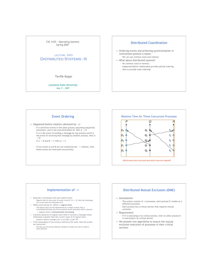
Relative Time for Three Concurrent Processes

Which events are concurrent and which ones are ordered?

Implementation of →

  • Associate a timestamp with each system event

– Require that for every pair of events A and B, if A → B, then the timestamp

  • f A is less than the timestamp of B
  • Within each process Pi, define a logical clock

– The logical clock can be implemented as a simple counter that is incremented between any two successive events executed within a process

  • Logical clock is monotonically increasing
  • A process advances its logical clock when it receives a message whose

timestamp is greater than the current value of its logical clock – Assume A sends a message to B, LC1(A)=200, LC2(B)=195

  • If the timestamps of two events A and B are the same, then the events

are concurrent – We may use the process identity numbers to break ties and to create a total ordering

Distributed Mutual Exclusion (DME)

  • Assumptions

– The system consists of n processes; each process Pi resides at a different processor – Each process has a critical section that requires mutual exclusion

  • Requirement

– If Pi is executing in its critical section, then no other process Pj is executing in its critical section

  • We present two algorithms to ensure the mutual

exclusion execution of processes in their critical sections

slide-2
SLIDE 2

DME: Centralized Approach

  • One of the processes in the system is chosen to coordinate the

entry to the critical section

  • A process that wants to enter its critical section sends a

request message to the coordinator

  • The coordinator decides which process can enter the critical

section next, and its sends that process a reply message

  • When the process receives a reply message from the

coordinator, it enters its critical section

  • After exiting its critical section, the process sends a release

message to the coordinator and proceeds with its execution

  • This scheme requires three messages per critical-section

entry:

– request – reply – release

DME: Fully Distributed Approach

  • When process Pi wants to enter its critical section, it

generates a new timestamp, TS, and sends the message request (Pi, TS) to all processes in the system

  • When process Pj receives a request message, it may

reply immediately or it may defer sending a reply back

  • When process Pi receives a reply message from all other

processes in the system, it can enter its critical section

  • After exiting its critical section, the process sends reply

messages to all its deferred requests

DME: Fully Distributed Approach (Cont.)

  • The decision whether process Pj replies immediately to a

request(Pi, TS) message or defers its reply is based on three factors:

– If Pj is in its critical section, then it defers its reply to Pi – If Pj does not want to enter its critical section, then it sends a reply immediately to Pi – If Pj wants to enter its critical section but has not yet entered it, then it compares its own request timestamp with the timestamp TS

  • If its own request timestamp is greater than TS, then it

sends a reply immediately to Pi (Pi asked first)

  • Otherwise, the reply is deferred

– Example: P1 sends a request to P2 and P3 (timestamp=10) P3 sends a request to P1 and P2 (timestamp=4)

Undesirable Consequences

  • The processes need to know the identity of all other

processes in the system, which makes the dynamic addition and removal of processes more complex

  • If one of the processes fails, then the entire scheme

collapses

– This can be dealt with by continuously monitoring the state of all the processes in the system, and notifying all processes if a process fails

Token-Passing Approach

  • Circulate a token among processes in system

– Token is special type of message – Possession of token entitles holder to enter critical section

  • Processes logically organized in a ring structure
  • Unidirectional ring guarantees freedom from starvation
  • Two types of failures

– Lost token – election must be called – Failed processes – new logical ring established

Deadlock Handling

  • Prevention: Resource-ordering deadlock-prevention

=>define a global ordering among the system resources

– Assign a unique number to all system resources – A process may request a resource with unique number i only if it is not holding a resource with a unique number grater than i – Simple to implement; requires little overhead

  • Avoidance: Banker’s algorithm => designate one of the

processes in the system as the process that maintains the information necessary to carry out the Banker’s algorithm

– Also implemented easily, but may require too much overhead

slide-3
SLIDE 3

Prevention: Wait-Die Scheme

  • Based on a nonpreemptive technique
  • If Pi requests a resource currently held by Pj, Pi is

allowed to wait only if it has a smaller timestamp than does Pj (Pi is older than Pj)

– Otherwise, Pi is rolled back (dies)

  • Example: Suppose that processes P1, P2, and P3 have

timestamps 5, 10, and 15 respectively

– if P1 request a resource held by P2, then P1 will wait – If P3 requests a resource held by P2, then P3 will be rolled back

Prevention: Would-Wait Scheme

  • Based on a preemptive technique; counterpart to the

wait-die system

  • If Pi requests a resource currently held by Pj, Pi is

allowed to wait only if it has a larger timestamp than does Pj (Pi is younger than Pj). Otherwise Pj is rolled back (Pj is wounded by Pi)

  • Example: Suppose that processes P1, P2, and P3 have

timestamps 5, 10, and 15 respectively

– If P1 requests a resource held by P2, then the resource will be preempted from P2 and P2 will be rolled back – If P3 requests a resource held by P2, then P3 will wait

Deadlock Detection

Two Local Wait-For Graphs

Global Wait-For Graph

Deadlock Detection – Centralized Approach

  • Each site keeps a local wait-for graph

– The nodes of the graph correspond to all the processes that are currently either holding or requesting any of the resources local to that site

  • A global wait-for graph is maintained in a single coordination

process; this graph is the union of all local wait-for graphs

  • There are three different options (points in time) when the

wait-for graph may be constructed:

  • 1. Whenever a new edge is inserted or removed in one of the local wait-for

graphs

  • 2. Periodically, when a number of changes have occurred in a wait-for graph
  • 3. Whenever the coordinator needs to invoke the cycle-detection algorithm
  • Unnecessary rollbacks may occur as a result of false cycles

Local and Global Wait-For Graphs

slide-4
SLIDE 4

Detection Algorithm Based on Option 3

  • Append unique identifiers (timestamps) to requests

form different sites

  • When process Pi, at site A, requests a resource from

process Pj, at site B, a request message with timestamp TS is sent

  • The edge Pi → Pj with the label TS is inserted in the

local wait-for of A. The edge is inserted in the local wait-for graph of B only if B has received the request message and cannot immediately grant the requested resource

The Algorithm

  • 1. The controller sends an initiating message to each site in the

system

  • 2. On receiving this message, a site sends its local wait-for graph to

the coordinator

  • 3. When the controller has received a reply from each site, it

constructs a graph as follows:

(a) The constructed graph contains a vertex for every process in the system (b) The graph has an edge Pi → Pj if and only if

  • there is an edge Pi → Pj in one of the wait-for graphs, or
  • an edge Pi → Pj with some label TS appears in more than
  • ne wait-for graph

If the constructed graph contains a cycle ⇒ deadlock

21

Any Questions?

Hmm..

22

Reading Assignment

  • Read chapter 18 from Silberschatz.

23

Acknowledgements

  • “Operating Systems Concepts” book and supplementary

material by Silberschatz, Galvin and Gagne.