SLIDE 9 9
17
Monitor example
5” CRT Monitor 01
SPECIFICATION Standard: CCIR 625 Line 50Hz and RS 170 60Hz interlaced. Aspect ratio: Switchable between 4:3 and 4:1.77 Video impedance: 75 ohms ±2%. Input type: Differential Grey levels: 16 at 100 cd/m2 Video bandwidth: >12MHz -3dB Gain control: Contrast control on front panel Black level control: Brightness control on front panel Warm up time: 15 seconds after power Power requirements: 28V to MIL-STD-1275B Power consumption total: <20 watts (at 450cd/m2)
June 2006
18
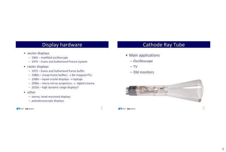
Monitor Example
Model SMT-3222 SMT4022 General
Screen Size 32" 40" Resolution (HxV) 1366 x 768 1920 x 1080 Pixel Pitch (mm) 0.511 x 0.511 (HxV) 0.46125 x 0.46125 (HxV) Brightness(cd/m2) 450 Contrast Ratio 4,000:1 (Dynamic Contrast Ratio 40,000:1) Response Time (ms) 8 (G-to-G) Viewing Angle (H/V) 178° / 178° Panel Lamp Life 50,000HR Display Colors 16.7M Horizontal Frequency 30 ~ 81KHz Vertical Frequency 56 ~ 85Hz Horizontal Resolution 600TV Lines Comb Filter 3D Sync Format NTSC : 3.5 / PAL : 4.43 / Secam
Feature
Screen Aspect Ratio 4:3 / 16:9 Language English / French / German / Italian / Portuguese / Russian / Spanish / Swedish / Chinese / Japanese / Korean / Turkish / Taiwanese
Professional Large LCD Monitor