
SLIDE 1
Digital or Analog
William Sandqvist william@kth.se
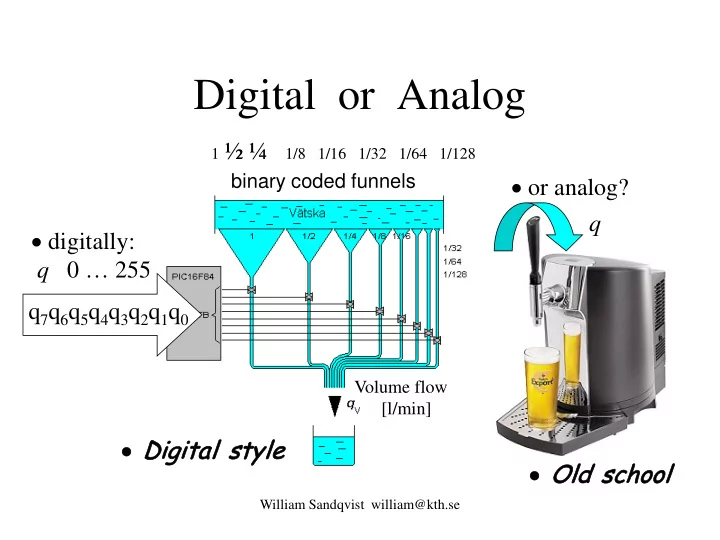
- digitally:
q 0 … 255 q7q6q5q4q3q2q1q0
- or analog?
1 ½ ¼ 1/8 1/16 1/32 1/64 1/128
q
- Old sc
d school
- Digi
gita tal s sty tyle
binary coded funnels
Volume flow [l/min]