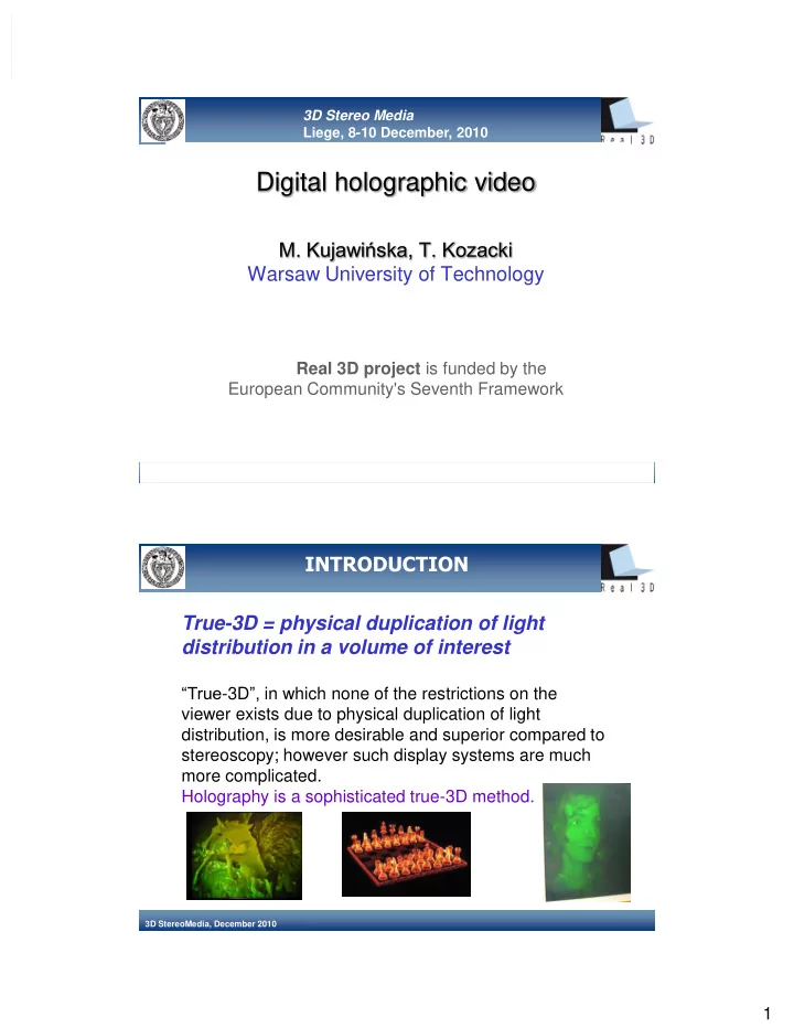
digital holographic video
play

Digital holographic video M. Kujawiska, T. Kozacki Warsaw - PDF document

3D Stereo Media Liege, 8-10 December, 2010 Digital holographic video M. Kujawiska, T. Kozacki Warsaw University of Technology Real 3D project is funded by the European Community's Seventh Framework 3D StereoMedia, December 2010 INTRODUCTION


  1. 3D Stereo Media Liege, 8-10 December, 2010 Digital holographic video M. Kujawińska, T. Kozacki Warsaw University of Technology Real 3D project is funded by the European Community's Seventh Framework 3D StereoMedia, December 2010 INTRODUCTION True-3D = physical duplication of light distribution in a volume of interest “True -3D ”, in which none of the restrictions on the viewer exists due to physical duplication of light distribution, is more desirable and superior compared to stereoscopy; however such display systems are much more complicated. Holography is a sophisticated true-3D method. 3D StereoMedia, December 2010 1

  2. Goodman “Fourier Optics” Holography greek holos – whole (entire) grapho – write (record) The two step method for lensless recording of 3D information about an object in the form of a complex amplitude Object amplitude Object phase A(x,y)= A o (x,y) exp( F (x,y)) Optical holography requires: coherent (laser) light, high resolution recording material Digital holography requires: Coherent light, high resolution and big aperture CCD/CMOS 3D StereoMedia, December 2010 Fundamental challenge in holographic video Goal: achieving a high enough space-bandwidth product of capture and display system to meet the image size and view angle requirements for the viewer.  a large view angle is possible only with very small interference fringes (and thus small pixels),  a large image translates to a large aperture of CCD and light modulator Therefore what’s necessary is a massive number of very small pixels. 3D StereoMedia, December 2010 2

  3. MIT holographic systems: Mark-I, II, III Mark I: 1D light modulation by AOM + mechanical scanning Mark II 18 channel AOM+ bank of scanning mirrors Controlled by custom based computer Cheops 150x75x150 mm 3 , 30 deg view angle Mark III based on surface acoustic wave (scanning replaced by HOE)  440 scan lines, 30 Hz  80 x 60 x 80 mm 3, 24 deg view angle P. St.-Hilaire. Scalable optical architectures for electronic holography. In Ph. D. Thesis, 3D StereoMedia, December 2010 Program in Media Arts and Sciences, MIT , 1994. See Real (2007) Observer window 20’’ prototype, 0.5 deg, eye tracking – matching Observer Window in real time Approach: reconstruct only that part of the object wavefront that hits the eye pupil of observer. Vertical paralax only. Separate observer window for each eye generated by spatial or temporal multiplexing S. Reichelt,et al. Large holographic 3D displays for tomorrowŠs TV and monitors - solutions, challenges, and prospects. IEEE Lasers and Electro-Optics Society, 2008. LEOS 2008. 21st Annual Meeting of the , pages 194 – 195, 2008. R. Häussler, A. Schwerdtner, and N. Leister. Large holographic displays as an alternative to stereoscopic displays. volume 68 03, page 68030M. SPIE, 2008. 3D StereoMedia, December 2010 3

  4. QinetiQ: Active Tiling System Features: For store and display CG holograms High frame rate of medium complexity Electr. address EASLMs – image generator Holograms written at high res. OASLM Parallel approach Monochromatic or frame – sequential-colour 1x4 channel AT unit Spatial multiplex 3x8 bilion-pixel Full-paralax Full-colour 3D image J. Hahn, H. Kim, Y. Lim, G. Park, and B. Lee. Opt. Express , 16(16):12372 – 12386, 2008. 3D StereoMedia, December 2010 Dynamic holographic stereogram LCOSes display holograms calculated from 2D images Achieved viewing angle 22.8 deg (2008, Korea) Joonku Hahn, Hwi Kim, Yongjun Lim, Gilbae Park, and Byoungho Lee. Wide viewing angle dynamic holographic stereogram with a curved array of spatial light modulators. Opt. Express , 16(16):12372 – 12386, 2008 3D StereoMedia, December 2010 4

  5. Conclusions from the overview The existing holographic systems are based on CG holograms but holograms of real objects Digital holography for 3D and 4D real- world objects’ capture, processing, and display OULU, Bilkent, WUT, EPFEL, BIAS, CNR Holoeye, LynceeTech, NUIM, 3D StereoMedia, December 2010 Real 3D Holographic video Registration Reconstruction Numerical CGH Numerical Optical Digital Holograms Optical A/D: CCD/CMOS 3D static & Cyfrowe hologramy Digital holograms dynamic scenes Data processing Aim of EU project Cal. Complex amplitude Real 3D Reduction of information Quality improvement Manipulation of 3D object 3D StereoMedia, December 2010 5

  6. Data displayed: Computer generated holograms Multi GPU systems (HORN6) Determination Complex Coding, Model of Γ (x,y,z) amplitude Processing Object/scene Fouriera Hol., Registration distribution 3D/4D Fresnela Hol., Konwersja C/A of the object Stereogram, wavefront ............... Cloud of points Triangle mesh 2D images SLM Photometric representation 3D scene visualization Eye tracking module 3D StereoMedia, December 2010 Real3D holographic video system  Application of inline Fresnel holograms  Capture of different perspectives of an object by multiple high resolution CCD/CMOS cameras in circular configuration  Display of holograms by multiple phase-only SLMs in circular configuration  Matching the parameters of capture and display systems  Coding and compression of DHs for high quality data transfer  Data processing of DHs into object phase data for display at SLMs 3D StereoMedia, December 2010 6

  7. Capture system - Multi CCD system (6) - Circular configuration -Normal of CCDs directed to object Otherwise: -Optical field might not fill detector - Optical field might be nor recorded due to high frequencies -Inline hologram registr.: PSDH (static) Fresnel (dynamic) - best use of spatial bandwidth - but need to remove DC and TI - good 3Dperception Basler piA2400 -12gm (2456x2058, 3.45m m) 3D StereoMedia, December 2010 Capture system 6 CCDs Source : Impulse laser 6ns Problem low fill factor 3D StereoMedia, December 2010 7

  8. Capture system 6 CCDs 3D StereoMedia, December 2010 Removal of DC and twin image terms from inline holograms Phase shifting holography Reconstruction Requires capture of at least 3 DH of inline hologram Reconstruction of a single DH 3D StereoMedia, December 2010 8

  9. Display system – Illumination along normal Multi LCOS SLMs Liquid Crystal on Silicon SLM Holoeye 1080P Pixel size 8 m m Advantage: the captured optical field is directly reconstructed on SLMs Disadvantage: complicated opto- mechanical realization 3D StereoMedia, December 2010 Reconstruction system – single illumination direction Advantages: Flexible system Easy to adjust and calibrate Problem: the phase function at SLMs should include the tilt LCoS display – HEO 1080P Phase only (res. 1080x1920, pp. 8 m m) 3D StereoMedia, December 2010 9

  10. Wide angle tilt processing angorithm Tilt 0 ° Tilt 10 ° Tilt 20 ° Tilt 30 ° Tilt 40 ° Without tilt procedure With tilt procedure With tilt procedure 3D StereoMedia, December 2010 Coupling the capture and display systems Mismatch in geometrical and optical features of both systems N1=N2 Size of Wavelength pixels Longitudinal Angular magnification Reconstruction distance Transverse l l D l D 2 rec   reg rec  reg   rec 2 M M M z z M l t rec reg l t l l D D M 2 reg t rec rec reg reg z reg - distance between object and detector, l reg/rec - wave length used during registration and reconstruction D reg/rec - pixel size of CCD and SLM respectively 3D StereoMedia, December 2010 10

  11. Holographic display: Main modules Multi SLMs Module Control & Data Processing CPU Illumination Nd:Yag: l =532nm Naked eye observation Directional diffuser Observation Through eyepiece 3D StereoMedia, December 2010 Display SLMs & Real images electronics Colimator Laser& electronics SLMs Mirrors  hologram reconstruction distance: 400 – 700 mm,  observation of real Configuration for FF=0.6 (but imaginary) image 3D StereoMedia, December 2010 11

  12. Reconstruction of static object 6 views of different object perspectives as reconstructed by single SLMs 3 different perspectives as seen by camera from combined image 3D StereoMedia, December 2010 Simulations for newest JVC SLM JVC SLM (simulation parameters) Output: Resolution: 8000 x 4000 pixels, pixel size 4.8 µm VFOV = 111 [mm] Distance between eyes db = 65 [mm], No gaps FF(for both capture and display) =1 i 6 SLMs Allowed a certain Reconstruction distance: 1000 [mm], Observer’s movement 3D StereoMedia, December 2010 12

  13. Whish list  Increase aperture (capture/display devices) and decrease the size of pixels  CCD/CMOS at flexible substrate (circular configuration)  Solutions (optical+ numerical) for gaps problem  Increase the quality of visualization the wavefront in space  Efficient solutions for video capture and data transfer 3D StereoMedia, December 2010 OULU (Finland) BIAS (Germany) PW (Poland) NUIM (Ireland) Holoeye (Germany) CNR (Italy) PFEL (CH) Linceetech (CH) Real 3D project is funded by the European Community's Seventh Framework Programme FP7/2007-2013 under grant agreement n ° 216105 3D StereoMedia, December 2010 13

Download Presentation
Download Policy: The content available on the website is offered to you 'AS IS' for your personal information and use only. It cannot be commercialized, licensed, or distributed on other websites without prior consent from the author. To download a presentation, simply click this link. If you encounter any difficulties during the download process, it's possible that the publisher has removed the file from their server.

Recommend


More recommend