SLIDE 1
Holographic video system: require very high speed in generating the hologram
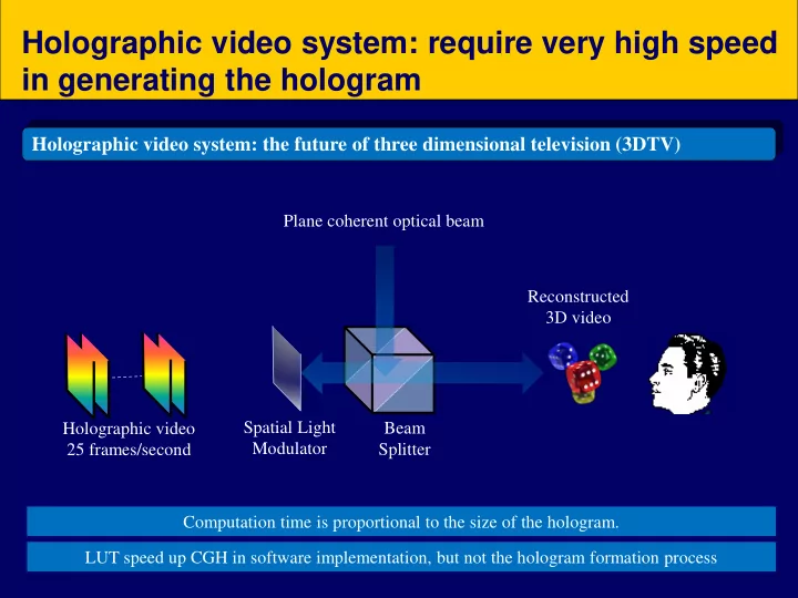
Holographic video system: the future of three dimensional television (3DTV)
Reconstructed 3D video Holographic video 25 frames/second Spatial Light Modulator Plane coherent optical beam Beam Splitter Computation time is proportional to the size of the hologram. LUT speed up CGH in software implementation, but not the hologram formation process
SLIDE 2
Hologram Generation
The problem is, each object point will contribute to the entire hologram.
A single point
Object
For multiple points, their individual wavefront is summed up in the hologram leading to large amount of calculations.
SLIDE 3 Computer Generated Holography
Computer Generated Hologram (CGH): Computes the sum of the wavefront contributed by all the object points in a three dimensional (3D) scene. 𝑃𝑙 𝑛, 𝑜 is the optical beam contributed by the kth object point. The more pixels in a hologram, the heavier will be the computation. As mentioned before, LUT methods do not improve the hologram formation process. 𝐼 𝑛, 𝑜 =
𝑙=0 𝐿
𝑃𝑙 𝑛, 𝑜
SLIDE 4 WRP is a hypothetical plane that is close to the object space. Within a short distance, each point contributes to a small region on the WRP For example, contribution of a single point
A single point
Object Wavefront Recording Plane (WRP)
Fast hologram generation: A WRP approach
- T. Shimobaba, N. Masuda, and T. Ito, "Simple and fast calculation algorithm for computer-generated hologram with
wavefront recording plane," Opt. Lett. 34, 3133-3135 (2009).
SLIDE 5 Fast hologram generation: A WRP approach
Generation of entire hologram directly from the
Generation of WRP
A single point
Object Virtual Diffraction Plane (WRP)
𝐼 𝑛, 𝑜 =
𝑙=0 𝐿
𝑃𝑙 𝑛, 𝑜 𝑊 𝑛, 𝑜 =
𝑙=0 𝐿
𝑥𝑠𝑞𝑙 𝑛, 𝑜
Support is much smaller than the size of the hologram
𝑥𝑠𝑞𝑙 𝑛, 𝑜 is the wavefront of the support for the kth point.
SLIDE 6 Step 2: Generate the WRP by summing the wavefront of each point at (u,v;zk) Step 3: Convert the WRP image to the hologram
Fast hologram generation: A WRP approach
Step 1: Load the point cloud of a 3D object from a CG model Where 𝑨𝑥𝑠𝑞 is the distance between the WRP and the hologram 𝑥𝑠𝑞𝑙 𝑛, 𝑜 = 𝐺𝑎𝑄 𝑛 − 𝑣, 𝑜 − 𝑤; 𝑨𝑙
𝑥ℎ𝑓𝑠𝑓 𝑣 − 𝜀 2 < 𝑛 < 𝑣 + 𝜀 2 , 𝑣 − 𝜀/2 < 𝑛 < 𝑣 + 𝜀/2
𝐼 𝑛, 𝑜 = 𝑊 𝑛, 𝑜 ∗ 𝐺𝑎𝑄 𝑛, 𝑜; 𝑨𝑤𝑒𝑞 𝑊 𝑛, 𝑜 =
𝑙=0 𝐿
𝑥𝑠𝑞𝑙 𝑛, 𝑜
SLIDE 7
Fast algorithm employing FFT,
Fast hologram generation: A WRP approach
The forward and backward of the Fourier Transform can be conducted in less than 10ms based on a commodity PC that is equipped with a graphic processing unit (GPU). 𝐼 𝜕𝑛, 𝜕𝑜 = 𝑊 𝜕𝑛, 𝜕𝑜 × 𝐺𝑎𝑄 𝝏𝒏, 𝝏𝒐; 𝒜𝒙𝒔𝒒 , and 𝐼 𝑛, 𝑜 = ℱ−1 𝐼 𝜕𝑛, 𝜕𝑜 𝐺𝑎𝑄 𝜕𝑛, 𝜕𝑜 = ℱ 𝐺𝑎𝑄 𝑛, 𝑜 , 𝑊 𝜕𝑛, 𝜕𝑜 = ℱ 𝑊 𝑛, 𝑜 ,
SLIDE 8 Computation is heavy if there are lots of object points, i.e. large value for K.
Trading off computation time with image quality
𝑊 𝑛, 𝑜 =
𝑙=0 𝐿
𝑥𝑠𝑞𝑙 𝑛, 𝑜 To decrease the computation time, the object image is down-sampled. However this leads to a sparse image that is dim in appearance. Down-sampled by 2 along horizontal and vertical
points reduced by 4 times.
SLIDE 9
- 1. Interpolate each object point image to its support area.
- 2. Compute the optical wave to the corresponding support on the WRP.
- 3. Supports are non-overlapping with each other.
- 4. Expand the WRP to the hologram.
Trading off computation time with enhanced image quality: Interpolative WRP (IWRP)
WRP
Object point Interpolated patch
SLIDE 10 Computation is reduced through down-sampling the object image, i.e. less object points. 𝑊 𝑛, 𝑜 = ራ
𝑙
𝑗𝑥𝑠𝑞𝑙 𝑛, 𝑜 Image quality is enhance with interpolation. Down-sampled by 2 along horizontal and vertical directions, following by
- interpolation. Object points
reduced by 4 times, but quality is good apart from slight blurring.
Trading off computation time with enhanced image quality: Interpolative WRP (IWRP)
A union operator is used as the interpolative wrps (iwrp) are non-overlapping.
SLIDE 11
Example on a color hologram generated with the 2D+depth and IWRP method
Color and depth map of the point cloud image of a cube, derived from the CG model below Color map Depth map Color hologram generated with the WRP method, and display with a high resolution LCoS device
SLIDE 12
Color holograms of different views of an earth model, generated with the WRP method, and display with a high resolution LCoS device
Example on a color hologram generated with the IWRP method
SLIDE 13 Sub-line method
,
- For most of the time, we maintain horizontal eye level in viewing.
- Panning horizontally to observe different views of a 3D scene along the
horizontal direction.
- Occasionally, move up and down to observe different views of a 3D scene
along the vertical direction. x (horizontal direction) y (vertical direction) L R
A hologram preserve optical waves of a 3D object from all directions, but we are interested in
- nly the change in view horizontally for most of the time.
SLIDE 14
Hologram Generation
To compute the optical wavefront for the entire hologram is large, even for a single point.
A single point
Object
But are all the calculations necessary if we are not interested in the change in view vertically? L R
SLIDE 15 Hologram Generation
To compute the optical wavefront for the entire hologram is large, even for a single point.
A single point
Object
A single hologram line can represent different views of the object point along the horizontal direction. However, there is no change in view as the eye level moves
- vertically. Computing a single hologram line involves much less operations.
L R
A hololine
SLIDE 16 Hologram Generation
If there is another point at a different vertical direction, simply add another hololine.
1st point
If there are more than one points on the same horizontal level, accumulate their
- ptical waves on the corresponding hololine.
L R
A hololine 2nd point
SLIDE 17 Sub-line method
,
- Partition the object space into a vertical stack of horizontal scan-planes.
- Generate a 1-D hologram sub-line for each scan-plane.
- The data-size of the hologram sub-lines is much smaller than that of a
hologram, hence can be transmitted at lower data-rate.
- At the receiving end, a 2-D hologram is generated from the sub-lines.
SLIDE 18
- Partition the object space into a vertical stack of horizontal scan-planes.
- Generate a 1-D hologram sub-line for each scan-plane.
- The data-size of the hologram sub-lines is much smaller than that of a
hologram, hence can be transmitted at lower data-rate..
- At the receiving end, a 2-D hologram is generated from the sub-lines.
Object space Scan-planes Sub-line generator Sub-line to hologram conversion hologram
Transmission A video holography framework based on sub-lines
P.W.M. Tsang, J.-P. Liu, W. Cheung, and T.-C. Poon, "Fast generation of Fresnel holograms based on multirate filtering," Appl. Opt. 48, H23-H30 (2009). P.W.M. Tsang, J.P. Liu, K.W.K. Cheung, and T.-C. Poon, "An enhanced method for fast generation of hologram sub- lines", Chinese Opt. Lett. 7, pp. 1092-1096 (2009).