DEVELOPMENT OF A COMPOSITE BONE PLATE FOR FIXATION OF A FRACTURED - - PDF document

development of a composite bone plate for fixation of a
SMART_READER_LITE
LIVE PREVIEW

DEVELOPMENT OF A COMPOSITE BONE PLATE FOR FIXATION OF A FRACTURED - - PDF document

18 TH INTERNATIONAL CONFERENCE ON COMPOSITE MATERIALS DEVELOPMENT OF A COMPOSITE BONE PLATE FOR FIXATION OF A FRACTURED TIBIA M.P.F. Sutcliffe 1 *, H.J. Kim 2 , S.H. Chang 2 , Y Huang 1 1 Department of Engineering, University of Cambridge,


slide-1
SLIDE 1

18TH INTERNATIONAL CONFERENCE ON COMPOSITE MATERIALS

1 Introduction Tibial fractures are a common injury due to falls or accidents in humans. For relatively simple fractures

  • f long bones internal fixation is a way of stabilising

the fracture to allow healing to take place. Bone plates, typically made of stainless steel or titanium, are screwed to the bone either side of the break to fix the two parts of the bone in place. More recently there has been a change from a more mechanical to a biological set of priorities for the fixation [1]. In particular it has been recognised that bone healing is enhanced by some small degree of movement at the healing callus; Perren [1] suggests that gap strains ranging from 2% to 10% are effective at promoting healing. For this reason more flexible internal fixations have been considered to allow such movement while providing appropriate support to the bone. Kim et al [2] have presented a comprehensive finite element (FE) study comparing a stainless steel fixation with comparable composite

  • devices. With the more flexible composite fixations

the strains at the fracture associated with muscle forces (typically 10% of body weight) generate strains at the healing callus within the range of 2 to 10% appropriate for healing, while the stiffer stainless steel fixation typically generates strains which are too low. In the current paper this model is extended in two

  • ways. It is hypothesized that the reduced modulus of

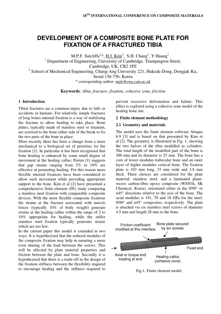
the composite fixation may help in ensuring a more even sharing of the load between the screws. This will be affected by plate material properties and friction between the plate and bone. Secondly it is hypothesised that there is a trade-off in the design of the fixation stiffness between the flexibility required to encourage healing and the stiffness required to prevent excessive deformation and failure. This effect is explored using a cohesive zone model of the healing bone site. 2 Finite element methodology 2.1 Geometry and materials The model uses the finite element software Abaqus 6.9 [3] and is based on that presented by Kim et al [2]. The geometry is illustrated in Fig. 1, showing the two halves of the tibia modelled as cylinders. The total length of the modelled part of the bone is 300 mm and its diameter is 25 mm. The bone has a core of lower modulus trabecular bone and an outer layer of higher modulus cortical bone. The fixation plate is 103 mm long, 15 mm wide and 3.8 mm

  • thick. Three choices are considered for the plate

material: stainless steel, and a laminated plane- weave carbon-fibre epoxy composite (WSN3k, SK Chemical, Korea), orientated either in the 0/90° or ±45° directions relative to the axis of the bone. The axial modulus is 191, 70 and 18 GPa for the steel, 0/90° and ±45° composites, respectively. The plate is attached via six stainless steel screws of diameter 4.5 mm and length 28 mm to the bone. Fig.1. Finite element model.

DEVELOPMENT OF A COMPOSITE BONE PLATE FOR FIXATION OF A FRACTURED TIBIA

M.P.F. Sutcliffe1*, H.J. Kim2, S.H. Chang2, Y Huang1

1 Department of Engineering, University of Cambridge, Trumpington Street,

Cambridge, UK, CB2 1PZ

2 School of Mechanical Engineering, Chung-Ang University 221, Huksuk-Dong, Dongjak-Ku,

Seoul 156-756, Korea

* corresponding author: mpfs@eng.cam.ac.uk

Keywords: tibia, fracture, fixation, cohesive zone, friction

Bone plate secured by six screws Healing callus (cohesive zone) Fixed end Axial or torque end loading at end Friction coefficient modified at this interface

slide-2
SLIDE 2

DEVELOPMENT OF A COMPOSITE BONE PLATE FOR FIXATION OF A FRACTURED TIBIA

A modification is made to Kim's model taking the fracture plane as oblique, with the normal to the plane making an angle of 15° relative to the axis of the bone. Further details of the geometry and material properties are given in [2]. 2.2 Contact modelling The contact between the bone and the plate is a critical aspect in controlling both the mechanical performance of the fixture and the healing process. The effect of friction at the interface is explored by assuming frictionless contact or Coulomb friction with coefficients of 0.2 or 0.4. For calculations exploring the effect of plate material and failure, sticking friction is assumed between the plate and

  • bone. Contact conditions between the screws and the

bone are modified from those used by Kim et al to facilitate convergence, with nodes being tied between the two components so that no relative motion is allowed between these surfaces. 2.3 Healing bone failure Cohesive zone elements are used to represent the healing callus. Abaqus software has a sophisticated range of options to model various types of

  • behaviour. Here the behaviour is modelled by a

traction-separation law, relating the axial and shear displacements across the gap to the corresponding element tractions [3]. Abaqus assumes a nominal gap of 1 unit, which in this case matches the assumed gap size of 1 mm. Following the prescribed Abaqus procedure the shear and axial moduli of the callus are then used to give the required elastic properties of the traction elements. To simplify the model only the stiffer cortical bone is modelled, with a Young’s modulus E varying with healing time according to Table 1 (taken from the analysis of Kim et al [2]). The shear modulus G is assumed to be equal to 0.38E. Time (weeks) Modulus (MPa) 4 0.10 8 25 12 31 16 75 Table 1. Change of healing bone modulus with time The failure behaviour of the elements is illustrated schematically in Fig. 2. In terms of the Abaqus

  • ptions, the model chosen is a linear softening

degradation model, quadratic in tractions, with a quadratic failure criterion. For the choice of parameters used the failure is governed by an effective failure strain εeq as defined by

2 2 2 1 2 2 s s t eq

ε ε ε ε + + = (1) where εt is the transverse strain normal to the fracture plane and εs1 and εs2 are radial and circumferential shear strains in the element. When εeq reaches a critical value, chosen in the analysis as 0.1, the element starts to degrade. Note that in the case either of pure tension or pure shear the failure strain equals 0.1. The traction-separation behaviour falls linearly up to a final equivalent strain of 0.2, at which point the element no longer carries a load. Because the Abaqus model only allows for failure in tension, axial tensile forces are applied when using this cohesive zone model. For the small displacement, sticking friction formulation used in these calculations, this tensile loading will give similar behaviour as the corresponding compressive load case which is physiologically appropriate. Fig.2. Cohesive zone failure model.

Transverse strain εt Quadratic damage initiation and final failure surfaces Shear strain εs Stress σ

0.1 0.1 0.2 0.2

Linear elastic loading Linear degradation

slide-3
SLIDE 3

18TH INTERNATIONAL CONFERENCE ON COMPOSITE MATERIALS

2.4 Loads One end of the bone is fixed and loads applied at the

  • ther end. In the initial analysis step, bolt tightening

forces of 2000 N are applied in each of the screws. Because of Poisson’s effects, this causes some

  • pening of the fracture gap which is eliminated by a

small (3 N) transverse load at the end of the bone. An axial load or torque loading is then applied to the end of the bone, either by appropriate pressure or concentrated forces. In this loading step the length of the bolts is held fixed, so that changes in the bolt forces are induced. 2.5 Solution details Non-linear geometric effects are not included, as the deformations are small except at the healing callus where it is felt that the simplicity and assumptions made in the failure model do not justify inclusion of geometric non-linearities. The effect of mesh refinement are explored. For calculations where details of the contact conditions are not critical, a relative coarse mesh is used, containing around 9600 elements in the bone, 2300 elements in the plate and 230 elements per screw. For calculations exploring contact conditions a finer mesh, with 80,000 elements in the bone, 7200 elements in the plate and 900 elements in each screw is used.

  • 3. Results

3.1 Load transfer from screws to bone It is hypothesised that the load may be transferred more evenly through the six screws with a lower modulus composite material. The shear force in each screw is found from a ‘free body cut’ in the Abaqus simulation, and this is converted to a nominal bearing load by dividing by the corresponding projected area of the bolt. This measure was chosen to assess how changes in shear forces might result in local failure of the bone and hence loosening of the

  • joint. It was found that there was considerably

variability in the distribution of forces, and this measure was sensitive to the mesh size. Hence in these calculations the finer mesh was used. However, this sensitivity also indicates that a number of factors may significantly affect screw forces in clinical practice: the details of how the screws are done up, changes in frictional conditions during the initial plate fixation and local geometric details at the fracture site. The effect of friction and plate material on the transfer of load into the bone is shown in Fig. 3, which plots the nominal bearing stress for the most highly loaded screw in each case. The bearing stress decreases with an increase in friction, as more load is transferred by friction at the bone-plate interface. Hence there is a reduced likelihood of failure at the screw-bone interface at these higher friction coefficients, although the increased shear stress may in itself induce damage or hinder the blood supply [1]. The composite plate gives a lower bearing stress on the bone than the stainless steel plate at the highest but realistic friction coefficient of 0.4 for an axial load equal to 200% of body weight. This is because the load is spread more evenly between the screws on account

  • f the lower mismatch in modulus between the plate

and the bone. Fig.3. Effect of friction and plate material on maximum nominal bearing stress in the screws. 3.2 Failure of the callus The cohesive zone model of the healing callus allows an examination of how progressive failure might occur due to overloads before the callus has had a chance to heal. Figure 4 shows the relationship between the applied axial load and the strain in the callus, in this case characterised by the equivalent strain εeq (defined by equation 1) at the mid-point of the callus. Material properties for the callus are taken for this illustration at 8 weeks. Without degradation there is a linear dependence, governed by the elastic behaviour of the various components.

0.2 0.4 2 4 6 8 10 Friction coefficient Nominal bearing stress (MPa)

200% body weight 10% body weight ±45 °composite stainless steel

slide-4
SLIDE 4

DEVELOPMENT OF A COMPOSITE BONE PLATE FOR FIXATION OF A FRACTURED TIBIA

Fig.4. Effect of callus damage on response, plotting the relationship between applied axial load and the equivalent strain εeq at the mid-point of the callus. On introducing the non-linear failure criterion a maximum is seen in the applied axial load corresponding to significant degradation in the

  • callus. For the case illustrated, the contribution to

stiffness from the healing callus is significant and the maximum applied load is a useful measure of the load that the joint could take without compromising the healing. Earlier in the healing process (0 and 4 weeks after surgery) the callus has little stiffness so that a maximum load is not seen. In this case the failure load is characterised as the load at which the midpoint of the callus has an equivalent strain equal to the failure initiation strain of 0.1. Using these alternative measures of failure, Fig. 5 plots the effect

  • f material and healing time on the axial load to

cause failure. Early in the healing phase the extra stiffness of the steel or 0/90° composite plate offers protection against overload, perhaps at the expense

  • f providing a less good environment for healing to

take place. By 8 weeks healing time, the bone now contributes significantly to the joint strength and the effect of plate material is less significant.

  • Fig. 5. Effect of material and healing time on the

axial load to give callus failure. 3.3 Tailoring plate elastic properties The above results show how the plate stiffness should be chosen to give sufficient movement without overloading the callus. In practice the plate stiffness can be altered both by changing material and by changing the thickness of the plate. The final choice then depends on the expected loads as a function of healing time. For example, if loads are to less than 10% of body weight (e.g. 70 N), then the composite plate is an appropriate choice. The steel plate is too stiff, though perhaps a thinner steel plate might be appropriate. In addition composite materials can be tailored to suit a range of load cases. This is illustrated by considering combinations of axial and torque loading on the tibia, for the case where there is no significant contribution of the callus to the overall stiffness (i.e. 0 weeks after surgery). Again failure is characterised by the load where the equivalent strain at the midpoint of the callus equals 0.1. Figure 6 plots a failure surface, in terms of the applied axial and torque loads, for the three materials. By changing the lay-up of the composite material the failure surface can be adjusted either to provide optimum strain in the callus so as to promote healing, or conversely to prevent overloading of the callus for a combination of load cases.

  • Fig. 6. Failure surface corresponding to onset of

failure at the midpoint of the callus with combined axial and torque loading.

0.05 0.1 0.15 0.2 0.25 500 1000 1500 Equivalent strain Axial load (N)

with damage no degradation

4 8 12 16 50 100 300 1000 3000 Healing time (weeks) Axial load (N)

0/90 °composite ±45 °composite stainless steel

100 200 300 400 500 1 2 3 Axial load (N) Torque load (Nm)

±45°composite 0/90°composite stainless steel

slide-5
SLIDE 5

18TH INTERNATIONAL CONFERENCE ON COMPOSITE MATERIALS

4 Summary A finite element model has been used to show how a composite bone fixation device compares in performance with an equivalent stainless steel plate. It has previously been shown [2] that the reduced modulus of the composite plate provides a better environment for healing in the early weeks after

  • fracture. The results of the new work demonstrate

that the composite plate also gives a more even transfer of load via screws from the plate into the bone for a realistic friction coefficient of 0.4. A cohesive zone model of failure of the healing callus has been used to illustrate how the stiffer steel plate provides a better protection against overloads in the early phases of healing, at the expense of providing a less good environment for healing. Finally it is shown that the composite lay-up can be adjusted to provide an optimum environment for healing, depending on the applied axial and torque loading. Acknowledgements The authors are grateful for support from a Korea Research Foundation Grant funded by the Korean Government (KRF-2008-220-D0003) and for Dr AC Durie’s tribological contributions. References

[1] Perren SM. Evolution of the internal fixation of long bone fractures. J Bone Joint Surg 2002;84-B:1093- 110 [2] Kim SH, Change SH, Jung HJ. The finite element analysis of a fractured tibia applied by composite bone plates considering contact conditions and time- varying properties

  • f

curing tissues. Comp.

  • Structures. 2010;92(9) 2109-2118

[3] Abaqus Version 6.9.1. 2009. Dassault Systèmes Simulia Corp, RI, USA