
SLIDE 1
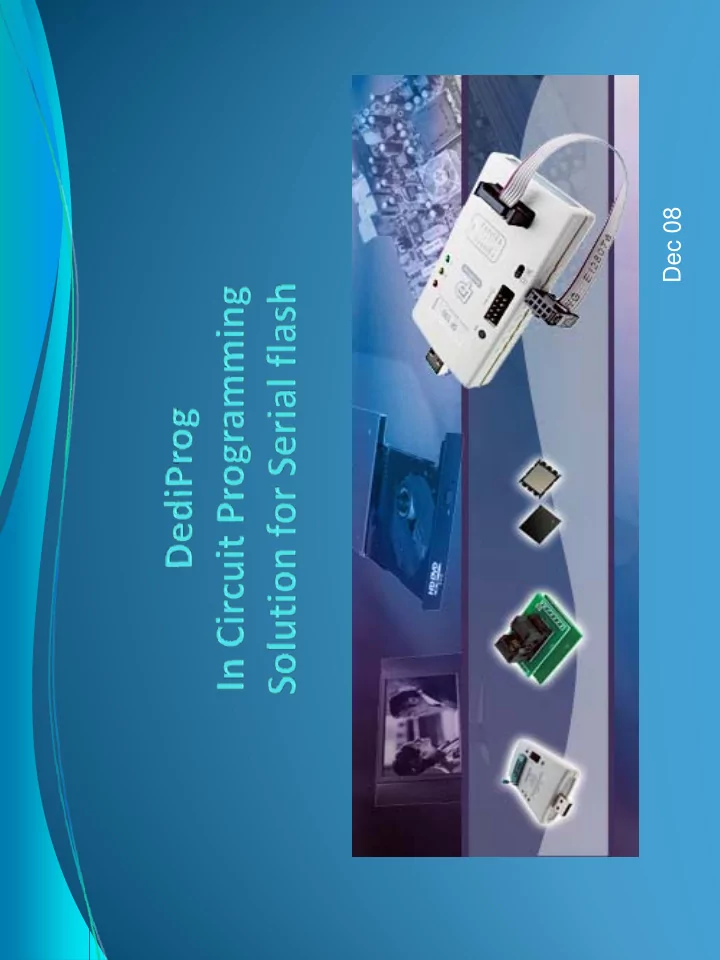
Dec 08 In Circuit Programming method (ICP) Introduction g g ( ) - - PDF document
Dec 08 In Circuit Programming method (ICP) Introduction g g ( ) Benefit of the highest update flexibility for development, debugging, production and repairing by using our In Circuit Programming production and repairing by using our In
IAP = In Application Programming (use the application software to update the Flash) ISP = In System Programming (Use an external tool to update the Flash through the application controller) ICP = In circuit Programming (Use external tool to update directly the Flash on board)
Application communication (IAP) Or External tool (ISP)
Bus
IAP and ISP are often limited by: External low bus interface Transfer through chipset Chipset SPI interface (For Die cost reduction, the chipset
Bus (Jtag..)
SPI interface
( , p SPI buffer is often reduced to few bytes 8, 16 and optimized for fast read but not for fast Serial Flash Programming)
SPI interface
SPI interface
SF100 Or SF300
Or SF300
In Circuit Programming is
Optimum frequency O ti SPI b ff (256B t )
Optimum SPI buffer (256Bytes) No limitation due to cost reduction
ICP connector
USB For computer communication LCD screen For application
USB mode
USB & SA mode communication LCD screen to monitor the Stand Alone mode LED for
ICP connector For application Power for Stand Alone mode
LED for
Start button For Stand Alone mode USB For computer communication
Socket adaptor Buzzer
Application Board
SPI Programmer Header (Top view)
Red wire: Vcc
Application ICP Pin Header Application Board
SF100
ICP Cable
6 MOSI MISO 5 4 CLK CS 3 2 GND Vcc 1 8 I/O3 Empty 7
Mistake Proof pin p
Pin Name of signal Description
1, 2
Vcc, Gnd
Vcc supplied from the programmer to the Serial Flash 3, 4, 5, 6
CS1, CLK, MISO, MOSI
SPI signals 8
IO3
Used to reset the Chipset or switch off the Mosfet 7
Mistake proof pin
Prevent from wrong connection 7
Mistake proof pin
Prevent from wrong connection
Mem ory supplied By SF1 0 0 or SF3 0 0 Diode to not supply the application w ith the program m er Chipset not supplied potential Leakage Currents
ICP connector
Serial Flash to be m easured ( threshold on resistors I = U/ R) SPI Serial resistors (33 or 47 Ohm) to:
it th l k t i th hi t d i ICP Conditions:
signals on its SPI IO even if
update not supplied (small leakage current in the chipset)
Mosfet to not supply the application w ith the program m er Vcc
Mem ory supplied
w ith the program m er Vcc
Chipset not supplied By program m er No Leakage currents
ICP connector
Serial Flash Flash
Mosfet to isolate the chipset during the I CP update w ith application OFF:
Conditions:
Application ON MOSFET ON
li d Chipset reset by program m er I O3
Chipset supplied
Mem ory supplied By application only Chipset reset by program m er I O3 before starting the SF update SPI Outputs in High I m pedance during reset or any other m odes ICP connector m odes..
SPI Serial resistors (33 or 47 Ohm) to: Filter the SPI signals overshoots and undershoots on edges Conditions:
modes..)
Mem ory supplied By application only
Chipset supplied
SPI outputs isolated by By application only SPI outputs isolated by Mosfet ( CS. CLK, MOSI ) ICP connector
Serial Serial Flash
SF1 0 0 and SF3 0 0 I O3 connected to the Mosfet gates. Mosfet are supplied by the application but sw itched off by the I O3 during the I CP update SPI I nput doesn’t need to be isolated ( MI SO) the I O3 during the I CP update
Conditions:
User can test all the com binations: S OS S i l i Connect I O3 to the Mosfet gate or application reset SPI MOSFET or Serial resistors Vcc Mosfet or Diode or shortcut gate or application reset Serial Flash Connected to the application ( Serial Flash Footprint) Test points are used to check The signals w ith oscilloscope Connect SF1 0 0 Or SF3 0 0
's-Hertogenbosch - Den Dungen - The Netherlands
ELTAN B.V. - Het Schild 13 - 5275 EB Den Dungen - P.O. Box 29 - 5275 ZG Den Dungen - The Netherlands Tel:+31 (0)73-5944660 - Fax:+31 (0)73-5941187 - E-mail: info@eltan.com - WEB: www.eltan.com Kvk: 1810499 - BTW / VAT no: NL807380507B01 - Bank: 51.32.90.583 ABN-AMRO
Your PC and Communication Technology Partner
Eltan is a European advanced engineering services company and the “core” competence is PC and Communication technology. Eltan provides specialized high-quality engineering services for hardware, Bios and operating systems as well as complete system solutions. Eltan is a Master distribution and development partner from Phoenix Technologies. Our engineers have experience and implemented Phoenix products since 1988. Eltan customizes the BIOS code of Phoenix to the customer hardware platform and offers object and source code license agreements fit for industrial and embedded suppliers. Eltan offers these development, engineering and customization services for Phoenix SecureCore Tiano, SecureCore, Embedded BIOS, Phoenix Award Bios, Phoenix GenSW BIOS, UEFI and full legacy compliant. Eltan engineers have implemented hundreds of customer specific BIOS-based features. To name some: Console redirect, ACPI, Security, pre-boot communication, Boot from SD, USB and 1394. Eltan designs and brings leading edge hardware to production. Eltan is specialized in designing customer specific boards based on x86 technology. Eltan covers the Intel, AMD and VIA Technologies standard and embedded processor lines. This includes Embedded Controller and FPGA combined hardware and software solutions. Some examples of products are: Motherboards (Industrial, embedded, and regular), Information Appliances, PC on a Chip based board solutions, Server blades, Network switches. Eltan's expertise ensures a planned and controlled design cycle enabling successful production startup, approvals & certification and meeting your planned time to market. Eltan supports you with Operating systems and Driver development for Microsoft Windows CE, XP, 2000, Vista, Windows 7, Server 2008 and Linux. Eltan's experience with File System Filter Drivers, Boot loaders (e.g. for Windows CE), Hardware Device Drivers, Filter Drivers and Operating System Configuration improves your time to market and will reduce the overall project cost Eltan offers licensing and engineering support for the Phoenix family of products. These products are targeted at board and system manufacturers and reduce support cost and add value to the customer’s products. Based on the in house BIOS expertise and the Phoenix Partnership Eltan provides engineering services to create Bios Protected Applications. Eltan reduces your time to market for industrial, consumer electronics and Information Appliance
system engineering.