
SLIDE 1
Davis-Besse Davis-Besse Nuclear Power Station Nuclear Power Station
April 4, 2003 1
Davis-Besse Nuclear Power Station Reactor Vessel Incore Monitoring - - PowerPoint PPT Presentation
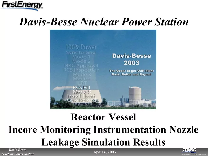
Davis-Besse Nuclear Power Station Reactor Vessel Incore Monitoring Instrumentation Nozzle Leakage Simulation Results 1 Davis-Besse Davis-Besse April 4, 2003 Nuclear Power Station Nuclear Power Station Agenda Opening Remarks . . . . . . .
Davis-Besse Davis-Besse Nuclear Power Station Nuclear Power Station
April 4, 2003 1
Davis-Besse Davis-Besse Nuclear Power Station Nuclear Power Station
April 4, 2003 2
Davis-Besse Davis-Besse Nuclear Power Station Nuclear Power Station
April 4, 2003 3
Davis-Besse Davis-Besse Nuclear Power Station Nuclear Power Station
April 4, 2003 4
Davis-Besse Davis-Besse Nuclear Power Station Nuclear Power Station
April 4, 2003 5
Restart Overview Panel Restart Overview Panel
Return to Service Plan Return to Service Plan
Containment Health Containment Health Assurance Plan Assurance Plan Randy Fast Randy Fast Program Compliance Plan Program Compliance Plan Jim Powers Jim Powers Restart Action Plan Restart Action Plan Lew Lew Myers Myers Reactor Head Reactor Head Resolution Plan Resolution Plan Bob Bob Schrauder Schrauder System Health System Health Assurance Plan Assurance Plan Jim Powers Jim Powers Restart Test Plan Restart Test Plan Randy Fast Randy Fast Management and Human Management and Human Performance Excellence Performance Excellence Plan Plan Lew Lew Myers Myers
Davis-Besse Davis-Besse Nuclear Power Station Nuclear Power Station
April 4, 2003 6
Davis-Besse Davis-Besse Nuclear Power Station Nuclear Power Station
April 4, 2003 7
B&W Nozzle Configuration Modified IMI nozzle (inside of reactor vessel)
Davis-Besse Davis-Besse Nuclear Power Station Nuclear Power Station
April 4, 2003 8
Davis-Besse Davis-Besse Nuclear Power Station Nuclear Power Station
April 4, 2003 9
B&W Current Nozzle Configuration EDF Nozzle Configuration
Original Configuration
Davis-Besse Davis-Besse Nuclear Power Station Nuclear Power Station
April 4, 2003 10
IMI Nozzles at Bottom of Reactor Vessel (Post-cleaning)
Davis-Besse Davis-Besse Nuclear Power Station Nuclear Power Station
April 4, 2003 11
Davis-Besse Davis-Besse Nuclear Power Station Nuclear Power Station
April 4, 2003 12
Davis-Besse Davis-Besse Nuclear Power Station Nuclear Power Station
April 4, 2003 13
Davis-Besse Davis-Besse Nuclear Power Station Nuclear Power Station
April 4, 2003 14
Davis-Besse Davis-Besse Nuclear Power Station Nuclear Power Station
April 4, 2003 15
Davis-Besse Davis-Besse Nuclear Power Station Nuclear Power Station
April 4, 2003 16
Davis-Besse Davis-Besse Nuclear Power Station Nuclear Power Station
April 4, 2003 17
Davis-Besse Davis-Besse Nuclear Power Station Nuclear Power Station
April 4, 2003 18
Test #1 (leak rate: 0.015 gpm) Nozzle OD showing leak path
Test Simulation Photo
Test #5 (leak rate: 0.0006 gpm) Crusty yellow deposit buildup
Test Simulation Photo
Davis-Besse Davis-Besse Nuclear Power Station Nuclear Power Station
April 4, 2003 19
– Primary water leaked at controlled rates (0.0004 to 0.015 gpm) into an annulus – Capillary tubing was used to achieve low leak rates – Tests were conducted at both Mode 1 and 3 plant operating temperatures and pressures – Leakage was collected for analysis – Test mockup was inspected after each test
Test #2 (leak rate: 0.0017 gpm) Inside of nozzle showing capillary tube arrangement
Test Simulation Photo
Davis-Besse Davis-Besse Nuclear Power Station Nuclear Power Station
April 4, 2003 20
Davis-Besse Davis-Besse Nuclear Power Station Nuclear Power Station
April 4, 2003 21
Test #1 (leak rate: 0.015 gpm) Inside of vessel head after removal of nozzle, showing eroded leak path Before cleaning
Test Simulation Photo
Test #1 (leak rate: 0.015 gpm) Post test view of nozzle/vessel head assembly
Test Simulation Photo
Davis-Besse Davis-Besse Nuclear Power Station Nuclear Power Station
April 4, 2003 22
Test #2 (leak rate: 0.0017 gpm) Nozzle OD showing buildup
Test Simulation Photo Test Simulation Photo
Test #2 (leak rate: 0.0017 gpm) Close-up view of head-to-nozzle annulus showing buildup of white deposits at exit of annulus
Davis-Besse Davis-Besse Nuclear Power Station Nuclear Power Station
April 4, 2003 23
Test #3 (leak rate: 0.0004 gpm) Post test view of nozzle/head assembly & thrust plate
Test Simulation Photo
Test #3 (leak rate: 0.0004 gpm) Nozzle surface deposits
Test Simulation Photo
Davis-Besse Davis-Besse Nuclear Power Station Nuclear Power Station
April 4, 2003 24
Test #4 (leak rate: 0.0012 gpm) Nozzle outer diameter showing buildup
Test Simulation Photo
Test #4 (leak rate: 0.0012 gpm) Close-up of head-to-nozzle annulus showing buildup of white deposit at exit of annulus
Test Simulation Photo
Davis-Besse Davis-Besse Nuclear Power Station Nuclear Power Station
April 4, 2003 25
Test #5 (leak rate: 0.0006 gpm) Crusty yellow deposit buildup on nozzle wall at annulus discharge
Test Simulation Photo
Davis-Besse Davis-Besse Nuclear Power Station Nuclear Power Station
April 4, 2003 26
Test #3 (leak rate: 0.0004 gpm) Nozzle surface deposits
Test Simulation Photo
Davis-Besse Davis-Besse Nuclear Power Station Nuclear Power Station
April 4, 2003 27
Davis-Besse Davis-Besse Nuclear Power Station Nuclear Power Station
April 4, 2003 28
Davis-Besse Davis-Besse Nuclear Power Station Nuclear Power Station
April 4, 2003 29
Sensor Element Non-Sensitive Tubing
Davis-Besse Davis-Besse Nuclear Power Station Nuclear Power Station
April 4, 2003 30
Davis-Besse Davis-Besse Nuclear Power Station Nuclear Power Station
April 4, 2003 31