
SLIDE 1
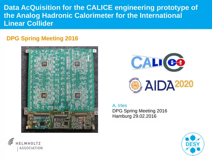
Data AcQuisition for the CALICE engineering prototype of the Analog Hadronic Calorimeter for the International Linear Collider.
DPG Spring Meeting 2016
- A. Irles
Data AcQuisition for the CALICE engineering prototype of the Analog - - PowerPoint PPT Presentation
Data AcQuisition for the CALICE engineering prototype of the Analog Hadronic Calorimeter for the International Linear Collider. DPG Spring Meeting 2016 A. Irles DPG Spring Meeting 2016 Hamburg 29.02.2016 Outline of the talk > The AHCAL
First and Last Name | Title of Presentation | Date | Page 2
Irles, A. | Hamburg, DPG Spring Meeting | 29th February 2016
First and Last Name | Title of Presentation | Date | Page 3
Irles, A. | Hamburg, DPG Spring Meeting | 29th February 2016
First and Last Name | Title of Presentation | Date | Page 4
Irles, A. | Hamburg, DPG Spring Meeting | 29th February 2016
First and Last Name | Title of Presentation | Date | Page 5
Irles, A. | Hamburg, DPG Spring Meeting | 29th February 2016
First and Last Name | Title of Presentation | Date | Page 6
Irles, A. | Hamburg, DPG Spring Meeting | 29th February 2016
First and Last Name | Title of Presentation | Date | Page 7
Irles, A. | Hamburg, DPG Spring Meeting | 29th February 2016
First and Last Name | Title of Presentation | Date | Page 8
Irles, A. | Hamburg, DPG Spring Meeting | 29th February 2016
First and Last Name | Title of Presentation | Date | Page 9
Irles, A. | Hamburg, DPG Spring Meeting | 29th February 2016
First and Last Name | Title of Presentation | Date | Page 10
Irles, A. | Hamburg, DPG Spring Meeting | 29th February 2016
First and Last Name | Title of Presentation | Date | Page 11
Irles, A. | Hamburg, DPG Spring Meeting | 29th February 2016
First and Last Name | Title of Presentation | Date | Page 12
Irles, A. | Hamburg, DPG Spring Meeting | 29th February 2016
First and Last Name | Title of Presentation | Date | Page 13
Irles, A. | Hamburg, DPG Spring Meeting | 29th February 2016
First and Last Name | Title of Presentation | Date | Page 14
Irles, A. | Hamburg, DPG Spring Meeting | 29th February 2016
First and Last Name | Title of Presentation | Date | Page 15
Damping Rings e- bunch compressor e+ bunch compressor Detectors e- source e+ source
e-e+ → HZ, Z → 2 leptons (ILD simulation) Higgs candidate decaying to 4 electrons (ATLAS 2012))
Irles, A. | Hamburg, DPG Spring Meeting | 29th February 2016
First and Last Name | Title of Presentation | Date | Page 16
Irles, A. | Hamburg, DPG Spring Meeting | 29th February 2016
First and Last Name | Title of Presentation | Date | Page 17
Irles, A. | Hamburg, DPG Spring Meeting | 29th February 2016
First and Last Name | Title of Presentation | Date | Page 18
Irles, A. | Hamburg, DPG Spring Meeting | 29th February 2016
First and Last Name | Title of Presentation | Date | Page 19
Irles, A. | Hamburg, DPG Spring Meeting | 29th February 2016