Converting from E/R to relational model Introduction In the last - - PDF document

converting from e r to relational model
SMART_READER_LITE
LIVE PREVIEW

Converting from E/R to relational model Introduction In the last - - PDF document

Converting from E/R to relational model Introduction In the last segment, we learned how to create an Entity-relationship model. However, creating the model is only half the task; we still need to convert the model into a usable database. Doing


slide-1
SLIDE 1

Converting from E/R to relational model

Introduction

In the last segment, we learned how to create an Entity-relationship model. However, creating the model is only half the task; we still need to convert the model into a usable database. Doing that usually requires two steps. First, we need to eliminate redundancy and other irregularities in the model we

  • developed. Second, because the ER model is more expressive than the relational model, we usually

need to simplify the model to make it compatible with the relational model.

Cleaning up the model

Eliminating redundancy

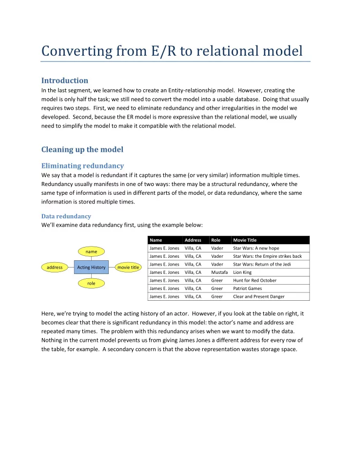
We say that a model is redundant if it captures the same (or very similar) information multiple times. Redundancy usually manifests in one of two ways: there may be a structural redundancy, where the same type of information is used in different parts of the model, or data redundancy, where the same information is stored multiple times. Data redundancy We’ll examine data redundancy first, using the example below: Here, we’re trying to model the acting history of an actor. However, if you look at the table on right, it becomes clear that there is significant redundancy in this model: the actor’s name and address are repeated many times. The problem with this redundancy arises when we want to modify the data. Nothing in the current model prevents us from giving James Jones a different address for every row of the table, for example. A secondary concern is that the above representation wastes storage space.

Name Address Role Movie Title James E. Jones Villa, CA Vader Star Wars: A new hope James E. Jones Villa, CA Vader Star Wars: the Empire strikes back James E. Jones Villa, CA Vader Star Wars: Return of the Jedi James E. Jones Villa, CA Mustafa Lion King James E. Jones Villa, CA Greer Hunt for Red October James E. Jones Villa, CA Greer Patriot Games James E. Jones Villa, CA Greer Clear and Present Danger name Acting History movie title role address

slide-2
SLIDE 2

We can remove the redundancy by splitting the acting history into two entity sets: actors and movies. This lets us decouple actor addresses from movies, since the two really aren’t related. This can be seen in the example above to the left. However, even though there is now less redundancy than before, we still have redundancy in the roles played by actors. Looking again at the table above, we can see that James Jones played the same role in multiple movies. We can capture that information by splitting role into a separate entity set is well, and making acted in a ternary relationship. The final model are shown in on the right side of the above example. Structural redundancy In the example above, actors and directors both have names and addresses; this structural redundancy suggests that actors and directors share a similarity that is not captured in the model (namely that both are people). In this case, it might be better to model directors and actors as subclasses of people, and to move the name and address attributes to the parent class. Once we do this, however, there are no attributes left in directors and actors, which further suggests that perhaps directors and actors are unnecessary in our model. In this particular case, the real information is stored in the two relationships, and we can simplify the model significantly by having people star in movies and direct movies. Doing so also eliminates the risk of data redundancy that could arise if somebody is both an actor and a director, which is quite common in the movie industry. Before we continue, it’s important to note that database design tools cannot provide very much help in removing structural redundancies. The tool simply has no way to know whether two name attributes are really the same. Consider if we had an entity set “movie studio” that also had a name and address. Even though the two entity sets—actor and movie studio—would look the same, it does not make sense to combine them.

name Actor role address title Movie Acted In name Actor name address title Movie Acted In Role

name address Actors name address Directors StarsIn Movies Directs name address People Directors StarsIn Movies Directs Actors name address People StarsIn Movies Directs

slide-3
SLIDE 3

Removing irregularities

Is quite common for a first attempt at an ER model to contain many irregularities. Redundancy is one form of irregularity, but not the only one. In this section, we highlight several other kinds of irregularities to watch out for. Attributes vs. entity sets It is sometimes unclear whether we should model something as an entity set

  • r an attribute. A good entity set should satisfy one or both of the following

conditions: it should contain more attributes than just a key, and/or it should participate in a one-to-many or many-to-many relationship. The example model to the right is bad because it represents actors’ names and addresses a separate entity sets, with an extra relationship to connect them. Unless the database we're designing needs to track actors with multiple addresses

  • r many actors living same address, this level of detail is unnecessary and gives undue importance to
  • addresses. In our example from the previous section, we split roles off into its own entity set because

the same role could appear in multiple movies. Otherwise, we would have left it as an attribute since it contains only a key (name). 1:1 relationships Sometimes, we end up with mandatory 1:1 relationships (e.g. all entities must participate). For example, look again at the Actors-LivesAt-Address model from the previous paragraph. If our database only tracks

  • ne address per actor, and requires every actor to have an address, there is no need for two separate

entities.1 Instead, we can combine the trio into a single “Actors” entity set with two attributes. Even if a relationship is non-mandatory, judicious use of NULL values (as if produced by a left join) may work well enough in practice to be worth the simplification.

Making compatible with the relational model

Several design patterns that make perfect sense in the ER model have to be converted are removed in

  • rder to play into the relational model.

Multi-valued attributes

The relational model does not allow multi-valued attributes, so we must convert all such attributes to entity sets as follows:

Subclasses

1 Splitting them apart may make query execution more efficient, but that is a topic for D43 or a grad course.

name Actors LivesAt address Address

slide-4
SLIDE 4

Relational model has no concept of classes

  • r inheritance, so these must be removed

before we can create a relational

  • database. Consider the example on the

right, where E1 and E2 are both subclasses

  • f E0. There are several ways to convert

this into a form compatible with the relational model. Option 1: move all attributes of E1 and E2 into E0, and add a new attribute (Atype) that identifies which subclass (if any) a given entity falls into. This is perhaps the simplest approach, but has some serious

  • drawbacks. First, it no longer prevents E0 and E1 from

participating in R2, so application logic would be required to enforce that constraint. Second, it does not allow something to be both E1 and E2 simultaneously (imagine if E0/E1/E2 were people/students/TAs, for example). Finally, it introduces redundancy and waste, because all entities have the A11 and A21 fields, whether they use them or not. Option 2: Remove E0 completely; move its attributes into E1 and E2 and split R1 into two new relationships—R11 and R12—that maintain the link to E3. This enforces the constraint that only E2 can relate to E4, but makes it much more difficult to work with the relationship that used to be called R1. Further, this arrangement is structurally redundant (same attributes in two different entity sets) and potentially data redundant (if some entity is a member of both E1 and E2). Option 3: Working to improve Option 1, merge E1 into E0 (since it is not involved in any relationships) but preserve E2 by adding a new relationship (RG2) to link it with its “base class.” This arrangement preserves the constraint that

  • nly E2 can relate to E4, and allows an entity to

be E1 and E2 simultaneously (mostly as a side effect), but keeps the problems that come with the Atype attribute (redundant attributes and space wastage). It also forces a join of E0-RG2- E2 in order to recover the full value of E2, though the performance impact may or may not matter in practice.

isA

slide-5
SLIDE 5

Option 4: Improving Option 3 further, we split both E1 and E2 into entity sets, and connect them to E0 with relationships RG1 and RG2,

  • respectively. At this point all redundancy is

replaced with foreign key joins, and all

  • riginal constraints are enforced. The only

real weakness is that both E1 and E2 require joins in order to reconstruct their full value. Which of the above four options (or some variant thereof) you use will depend on the particular scenario you face, and the requirements you need to meet. I personally favor Option 4 as the cleanest solution, unless the performance reduction from the extra joins is intolerable.

Weak entity sets

Recall that a weak entity set consists of entities whose attributes do not identify them uniquely; their identity arises, at least partly, from the supporting relationship some other entity set provides. While this is a nice concept in theory, it raises a real problem in practice: how does the supporting entity unique identify the weak entities that “belong” to it, among several weak entities that appear identical? For example, if the CS and physics departments both had network printers named “treekiller,” how would we know which treekiller is which in order to connect it with the proper supporting entity? The answer is that we can’t know using only the information implied by the model. We can extend the model in several ways to provide the missing information: Option 1: Replicate the “printers” entity set for each department: CS_printer, physics_printers, etc. Printers from different departments thus appear in unique namespaces, and we know which “treekiller” is which by looking at the entity set it belongs to. The downside

  • f this approach is the structural redundancy it

imposes—a new owned-by relationship set and printers entity set for every department! This approach does not scale well: a large university has dozens of departments, and it would not be fun to write a query that lists all printers named “treekiller” if each one comes from a different relation! In one sense, the supporting relationship isn’t even necessary—or useful—because we need to know which table to access for each tuple, rather than which tuples to search for. Option 2: Convert the weak entity into a normal entity by finding (or creating artificially) some key for it. In our

name Printer IP address name Department Owned by name Physics Printers IP address name Department Owned by name CS Printers IP address Owned by name Printer IP address name Department Owned by

slide-6
SLIDE 6

network printer scenario, for example, we might identify every printer by its MAC or IP2 address. This works well enough, but it’s no longer clear that the printer “belongs” to some department in the way the original weak entity status implied. It also requires us to keep the supporting relationship, because a given department probably owns several printers. Option 3: Embed the key of the supporting entity (or entities) directly in the weak entity. Conceptually, this makes good sense: a team member will always know which team she belongs to, and a host on a network always knows which network it is part of. Using foreign keys makes it trivial to identify printers uniquely, without masking which department owns them. Even better, it allows us to merge the supporting relationship with the weak entity, because every printer belongs to at most one department. We will see more examples of this optimization in the next section. As with subclasses, the best way to deal with weak entities depends on the situation. However, Option 3 is almost always the best idea, and it’s safe to treat an ER diagram with weak entities as equivalent to the kind generated for Option 3. Option 2 might make sense if the weak entity actually has some key that we already need to store for other reasons, but that really just means the “weak entity” wasn’t weak after all. Option 1 is almost always a really bad idea and should be avoided as much as possible.

Optimizing the resulting relational model

It turns out that the relational model can express certain patterns more compactly than the ER model, and knowing how to exploit those patterns can make you database designs cleaner and more compact.

Merging relationship sets into entity sets

Whenever you encounter a 1:1 or 1:N relationship, the relationship can be merged into the entity on the “1” side by embedding the other’s key as a foreign key. For example: Customers(id, name, …) Customers(id, name, …) OrderedBy(cust_id, order_id) becomes Orders(order_id, order_date, …) Orders(order_id, cust_id, order_date, …) In particular, this optimization applies to the subclass Option 4 (we can eliminate the relationship that connects parent and child classes by embedding the parent class key in the child class), and to weak entity sets when we use Option 3 (by embedding the supporting entity’s key in the weak entity). Note that, in the case of N:M relationships (such as actors to movies), the final database needs to keep the relationship because that’s the only way to identify which actors played in a movie, and which movies an actor played in.

2 Actually, keying by IP address would be a really bad idea, because IP addresses tend to change fairly often

name Printer IP address name Department Owned by dept name

slide-7
SLIDE 7

Selecting a good primary key

Very often, we encounter ER diagrams with complex, multi-attribute key structures that may even span multiple entity sets (in the case of weak entities). They make good homework problems and exam

  • questions. However there are many reasons to avoid complex keys in a real system:
  • Keys serve a different purpose than normal attributes. A tuple’s key is not just some detail, it

*is* the tuple in a very real sense (with the other attributes being the details). If we allow a normal attribute to serve as a key, we risk the tuple’s identity changing if the attribute ever

  • changes. Worse, there’s no real guarantee that a set of attributes from the real world is truly

unique (firstName, lastName? no. firstName,lastName,phone? usually. etc.) Finally, only non- NULL attributes can form part of a key, and we may want normal attributes to allow NULL values for other reasons.

  • Weak entities do not have enough attributes to uniquely identify a tuple, and so they will need

some artificial form of key material anyway (e.g. a foreign key from the supporting entity set).

  • Multi-attribute keys are redundant. For example, we could key Movies off title and year, but

that could easily require 30 bytes or more per key. In contrast, if we assume there will be fewer than four billion (2**32) movies for the foreseeable future, an artificially-assigned integer key would work quite well and would require only four bytes—a 7:1 compression ratio or better each time we use the Movies key as a foreign key in some other relation.

  • Multi-attribute keys break encapsulation. For example, imagine a doctor’s office foolish enough

to use the following relation in their database: Patient(firstName, lastName, phone, …) Besides the potential privacy concerns, any change to the way patients’ names and contact information are represented internally would require changing all relations with foreign keys to

  • Patients. Assigning a unique (and unchanging) patient ID to each patient solves both problems.
  • Computers are really, really good at working with integers. An integer-based join or sort can

easily be 2-4x faster than a string-based one, even without considering the overheads imposed by multi-column keys. For these reasons, the prevailing best practice is to use arbitrarily-assigned integer keys for relations whenever possible. In fact, many database engines, including sqlite3, always assign an integer key to each tuple even if you do specify something more complex, because it simplifies their underlying architecture.

slide-8
SLIDE 8

Quick reference: converting ER to relational

slide-9
SLIDE 9