
SLIDE 1
William Sandqvist william@kth.se
Control with binary code William Sandqvist william@kth.se Dec Bin - - PowerPoint PPT Presentation
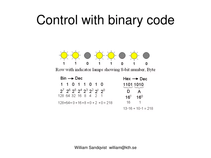
Control with binary code William Sandqvist william@kth.se Dec Bin Hex Oct 218 10 = 11011010 2 = DA 16 = 332 8 William Sandqvist william@kth.se Ex 1.1c Decimal to Binry binary weights: 1024 512 256 128 64 32 16 8 4 2 1 71 10 = ?
William Sandqvist william@kth.se
William Sandqvist william@kth.se
21810 = 110110102 = DA16 = 3328
William Sandqvist william@kth.se
binary weights: 1024 512 256 128 64 32 16 8 4 2 1
William Sandqvist william@kth.se
binary weights: 1024 512 256 128 64 32 16 8 4 2 1
William Sandqvist william@kth.se
binary weights: 1024 512 256 128 64 32 16 8 4 2 1
William Sandqvist william@kth.se
binary weights: 1024 512 256 128 64 32 16 8 4 2 1
William Sandqvist william@kth.se
William Sandqvist william@kth.se
William Sandqvist william@kth.se
William Sandqvist william@kth.se
x in common with y x together with y x in common with outside y
William Sandqvist william@kth.se
William Sandqvist william@kth.se
William Sandqvist william@kth.se
William Sandqvist william@kth.se
William Sandqvist william@kth.se
William Sandqvist william@kth.se
William Sandqvist william@kth.se
William Sandqvist william@kth.se
William Sandqvist william@kth.se
William Sandqvist william@kth.se
William Sandqvist william@kth.se
a) Draw a Venn Diagram for thre variables and mark all truth table minterms in the diagram. b) Minimize this function with the help of the Venn Diagram.
1 2 1 2 1 2 1 2 1 2
William Sandqvist william@kth.se
William Sandqvist william@kth.se
Orginal expression.
William Sandqvist william@kth.se
Simplified! Orginal expression.
William Sandqvist william@kth.se
Logical addition "+", OR, and logical multiplication "×", AND, broadly follows the usual normal algebraic distributive, commutative and associative laws (with one exception).
William Sandqvist william@kth.se
Rules
William Sandqvist william@kth.se
William Sandqvist william@kth.se
William Sandqvist william@kth.se
William Sandqvist william@kth.se
William Sandqvist william@kth.se
William Sandqvist william@kth.se
William Sandqvist william@kth.se
William Sandqvist william@kth.se
William Sandqvist william@kth.se
c b c a a a c b b b c a c b a bc a c b a c b a c b a bc a c b a c b a c b a c b a c b a c b a c b a c b c b a c b a c b a c b c b a c b a c b a + = + + + = = + + + = + + = + + + + + + + + = + + + + + + = = + + + + + + + = + + + + + + ) ( ) ( ) ( ) ( ) ( ) )( )( ( ) )( )( ( ) )( )( ( Duplicate!
William Sandqvist william@kth.se
William Sandqvist william@kth.se
Enter the name and output 1/0 for the following six gate types when the input signals are as shown in the figure.
William Sandqvist william@kth.se
AND Enter the name and output 1/0 for the following six gate types when the input signals are as shown in the figure.
William Sandqvist william@kth.se
AND OR 1 Enter the name and output 1/0 for the following six gate types when the input signals are as shown in the figure.
William Sandqvist william@kth.se
AND OR 1 XOR Enter the name and output 1/0 for the following six gate types when the input signals are as shown in the figure.
William Sandqvist william@kth.se
AND OR 1 XOR NAND Enter the name and output 1/0 for the following six gate types when the input signals are as shown in the figure.
William Sandqvist william@kth.se
AND OR 1 XOR NAND NOR 1 Enter the name and output 1/0 for the following six gate types when the input signals are as shown in the figure.
William Sandqvist william@kth.se
AND OR 1 XOR NAND NOR 1 XNOR 1 Enter the name and output 1/0 for the following six gate types when the input signals are as shown in the figure.
William Sandqvist william@kth.se
William Sandqvist william@kth.se
William Sandqvist william@kth.se
William Sandqvist william@kth.se
William Sandqvist william@kth.se
William Sandqvist william@kth.se
A combinatorical circuit with six input signals x5, x4, x3, x2, x1 and three output signals u2, u1, u0, is described in this way:
William Sandqvist william@kth.se
XOR AND XOR
5 4 2
NOT
William Sandqvist william@kth.se
XNOR AND XOR
2 5 2 5 1 1 2 5 1 1
William Sandqvist william@kth.se
NOT AND OR NOT
5 4 3 2 1 5 4 3 2 1 5 4 3 2 1 2 5 4 3 2 1 2
William Sandqvist william@kth.se
All the logical functions can be realized by using gate types AND and OR combined in two steps. We assume here that the input variables are also available in inverted form, if not then you of course inverters too.
One can realize the gate circuit direct from the truth table. Each "1" in the table is a minterm. The function is the sum of these
function is expressed in the SoP form (Sum of Products).
AND-OR logic, SoP-form
William Sandqvist william@kth.se
A locic function has this Truth Table: Write the function on SoP normal form: Write the function on PoS normal form:
William Sandqvist william@kth.se
A logical function has the following truth table. Specify the function of SoP-normal form (sum of products).
William Sandqvist william@kth.se
A logical function has the following truth table. Specify the function of SoP-normal form (sum of products).
William Sandqvist william@kth.se
c b a c b a c b a c b a f ⋅ ⋅ + ⋅ ⋅ + ⋅ ⋅ + ⋅ ⋅ =
A logical function has the following truth table. Specify the function of SoP-normal form (sum of products).
William Sandqvist william@kth.se
c b a c b a c b a c b a f ⋅ ⋅ + ⋅ ⋅ + ⋅ ⋅ + ⋅ ⋅ =
A logical function has the following truth table. Specify the function of SoP-normal form (sum of products).
William Sandqvist william@kth.se
Thus, if the function is to be "0" for a particular variable combination (a, b) for example (0.0) one is forming the sum (a + b). This sum could only be "0" for the combination (0.0). Such a sum is called a maxterm. The function is expressed as a product of all such maxtermer. Each maxterm contributes with a 0 from the truth-table. The function is said to be expressed in the PoS form (Product of Sums). Alternatively, one can focus on the truth table 0s. If a gate circuit reproduces the function 0's correct then of course the 1's are right to!
OR-AND logic, PoS form
William Sandqvist william@kth.se
A logical function has the following truth table. Specify the function of PoS-normal form (product of sums).
William Sandqvist william@kth.se
A logical function has the following truth table. Specify the function of PoS-normal form (product of sums).
William Sandqvist william@kth.se
) ( ) ( ) ( ) ( c b a c b a c b a c b a f + + ⋅ + + ⋅ + + ⋅ + + =
A logical function has the following truth table. Specify the function of PoS-normal form (product of sums).
William Sandqvist william@kth.se
) ( ) ( ) ( ) ( c b a c b a c b a c b a f + + ⋅ + + ⋅ + + ⋅ + + =
A logical function has the following truth table. Specify the function of PoS-normal form (product of sums).
William Sandqvist william@kth.se
William Sandqvist william@kth.se
A minimized function is given on SoP form (Sum of Products). Specify this function with minterms on SoP normal form, and with maxterms on PoS (Product of Sums) normal form.
William Sandqvist william@kth.se
+ + + + = = ⇒ = = ⇒ + + + + + = = + + + + + = + + = ) )( ( ) 7 , ( ) , , ( ) 6 , 5 , 4 , 3 , 2 , 1 ( ) 110 , 101 , 100 , 011 , 010 , 001 ( ) , , ( ) ( ) ( ) ( ) , , ( z y x z y x M z y x f m m z y x f z y x yz x z y x z xy z y x z y x z y y x z y x x z z y x z x z y y x z y x f
William Sandqvist william@kth.se
OR AND and NOT could be produces with NAND gates. For logic functions on the SoP form, you can change the AND-OR circuit to NAND-NAND "straight
The cost, the number of gates, will be the same!
William Sandqvist william@kth.se
OR AND and NOT can also be produced with NOR gates. For logic functions on the PoS form, you can replace the OR- AND circuit to NOR-NOR "straight off".
The cost, the number of gates, will be the same!
William Sandqvist william@kth.se
Change to NAND gates!
William Sandqvist william@kth.se
?
c b a
Algebraically: Change to NAND gates
William Sandqvist william@kth.se
Try out yourself …
William Sandqvist william@kth.se
Try out yourself …