
SLIDE 1
1.1
Circuit Basics
Mark Redekopp
1.2
VOLTAGE AND CURRENT
1.3
Current and Voltage
- Charge is measured in units of Coulombs
- Current – Amount of charge flowing
through a _________ in a certain ___________
– Measured in _________ = Coulombs per second – Current is usually denoted by the variable, I
- Voltage – Electric ________ energy
– Analogous to mechanical potential energy (i.e. _________ ) – Must measure ________________ points – Measured in Volts (V) – Common reference point: Ground (GND) = 0V
- Often really connected to the ground
Conductive Material
- -
- -
Higher Potential Lower Potential
5V 3V GND
Higher Potential Lower Potential 1.4
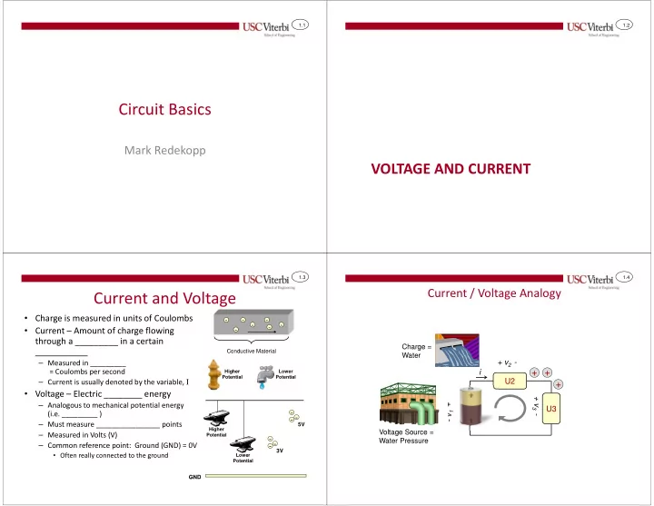
Current / Voltage Analogy
Voltage Source = Water Pressure
+ + +
Charge = Water
U2
U 1
U3 + v2 -
- v1 +
+ v3 - i