
Flaxer Eli - Process Control
Ch 5 - 1
Chapter 5 Computer Organization
Process Control
Flaxer Eli - Process Control
Ch 5 - 2
Outline
General Architecture of Computer
– CPU - MEM - I/O – Peripheral
Memory Hierarchy
– Main Memory – Auxiliary Memory
Input-Output Interface
Flaxer Eli - Process Control
Ch 5 - 3
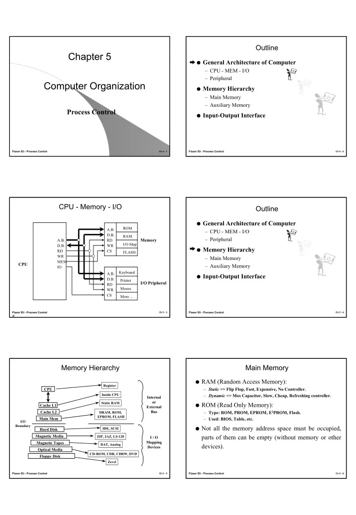
CPU - Memory - I/O
JZ
CPU Memory I/O Pripheral
A.B. D.B. RD WR CS A.B. D.B. RD WR CS A.B. D.B. RD WR MEM IO ROM RAM FLASH I/O Map Keyboard Printer More ... Mouse
Flaxer Eli - Process Control
Ch 5 - 4
Outline
General Architecture of Computer
– CPU - MEM - I/O – Peripheral
Memory Hierarchy
– Main Memory – Auxiliary Memory
Input-Output Interface
Flaxer Eli - Process Control
Ch 5 - 5
Memory Hierarchy
CPU Cache L1 Cache L2 Main Mem
I/O Boundary
Hard Disk Magnetic Media Magnetic Tapes Optical Media Floppy Disk
Register Inside CPU Static RAM DRAM, ROM, EPROM, FLASH IDE, SCSI ZIP, JAZ, LS-120 DAT, Analog CD-ROM, CDR, CDRW, DVD Zevel
Internal
- r
External Bus I / O Mapping Devices
Flaxer Eli - Process Control
Ch 5 - 6
Main Memory
RAM (Random Access Memory): – Static => Flip Flop, Fast, Expensive, No Controller. – Dynamic => Mos Capacitor, Slow, Cheap, Refreshing controller. ROM (Read Only Memory): – Type: ROM, PROM, EPROM, E2PROM, Flash. – Used: BIOS, Table, etc. Not all the memory address space must be occupied,