
3G Evolution
Chapter: 5 p 5
Wider-band single-carrier Wider band single carrier transmission
Payam Amani P A i@ it lth
Department of Electrical and Information Technology
Payam.Amani@eit.lth.se
3/26/2009 3G Evolution - HSPA and LTE for Mobile Broadband 1 1
Outline
- Why wider-band single carrier transmission?
- Equalization against radio- channel frequency selectivity
– Time domain linear equalization – Frequency domain equalization – Other equalizer strategies
- Uplink FDMA with flexible bandwidth assignment
- DFT- spread OFDM
– Basic principles DFTS OFDM i – DFTS-OFDM receiver – User multiplexing with DFTS-OFDM – Distributed DFTS-OFDM
3/26/2009 3G Evolution - HSPA and LTE for Mobile Broadband 2 2
Why wider-band single carrier transmission
- OFDM
Advantages: – Provides overal very high transmission bandwidth. – Robust to signal corruption due to radio channel frequency selectivity. g p q y y Drawbacks: – Large variations in the instantaneous power of transmitted signal.
- Reduced power amplifier efficiency
- High power amplifier cost
- Critical for uplink
– Some methods to reduce this power variations discussed in chapter 4 Some methods to reduce this power variations discussed in chapter 4.
- Limitations on the amount of reduction in these variations.
- Significant computational complexity and/or reduced link performance.
- wider-band single carrier transmission as an alternative for multicarrier
transmission especially for Uplink.
3/26/2009 3G Evolution - HSPA and LTE for Mobile Broadband 3
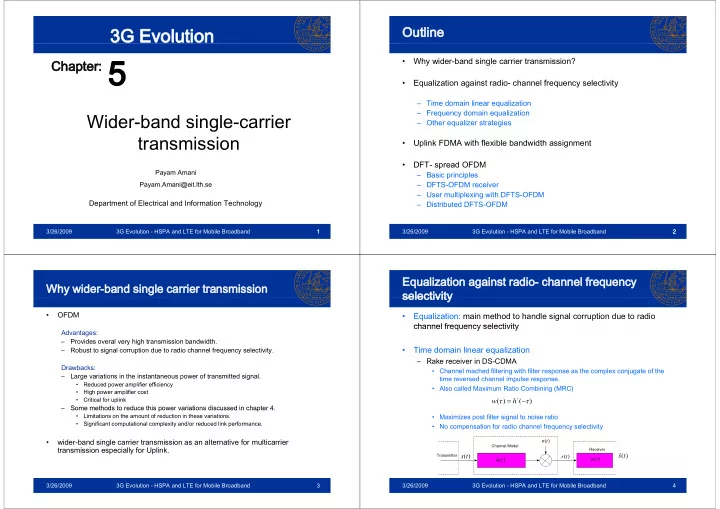
Equalization against radio- channel frequency selectivity selectivity
- Equalization: main method to handle signal corruption due to radio
channel frequency selectivity channel frequency selectivity
- Time domain linear equalization
q
– Rake receiver in DS-CDMA
- Channel mached filtering with filter response as the complex conjugate of the
time reversed channel impulse response. p p
- Also called Maximum Ratio Combining (MRC)
) ( ) (
*
τ τ − = h w
- Maximizes post filter signal to noise ratio
- No compensation for radio channel frequency selectivity
Transmitter Channel Model Receiver
) (t s
) (τ h ) (t n ) (t r ) (τ w
) ( ˆ t s
3/26/2009 3G Evolution - HSPA and LTE for Mobile Broadband 4