
1
4.1 Overview of Network layer
data plane
t l l
4.4 Generalized Forwarding and SDN
match
Chapter 4: outline
control plane
4.2 What’s inside a router 4.3 IP: Internet Protocol
IPv4 datagram format fragmentation action OpenFlow examples of
match-plus-action
v4 addressing network address
translation
IPv6 4-1
Network Layer: Data Plane (SSL)
11/2/2017
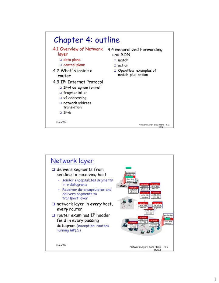
Network layer
delivers segments from
sending to receiving host
- sender encapsulates segments
into datagrams
application transport network data link physical network data link network data link
- Receiver de-encapsulates and
delivers segments to transport layer network layer in every host,
every router
router examines IP header
fi ld i i
application transport network network data link physical network data link physical data link physical network data link physical data link physical network data link physical network data link physical network data link physical network d li k
Network Layer: Data Plane (SSL) 4-2
field in every passing datagram (exception: routers
running MPLS)
network data link physical network data link physical data link physical network data link physical
11/2/2017