
SLIDE 1
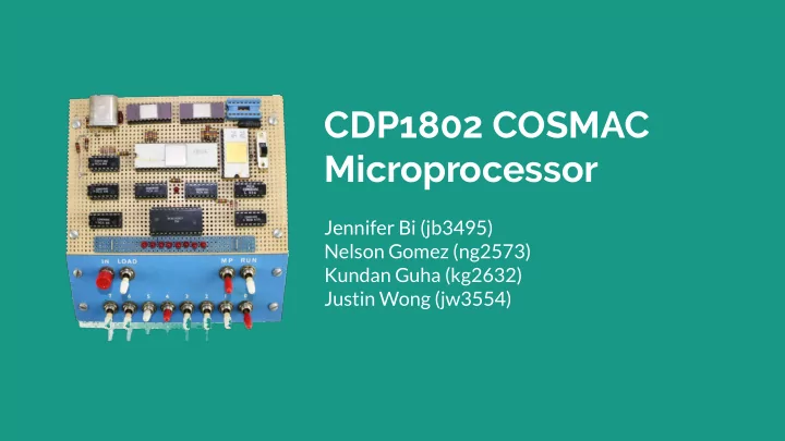
CDP1802 COSMAC Microprocessor
Jennifer Bi (jb3495) Nelson Gomez (ng2573) Kundan Guha (kg2632) Justin Wong (jw3554)
CDP1802 COSMAC Microprocessor Jennifer Bi (jb3495) Nelson Gomez - - PowerPoint PPT Presentation
CDP1802 COSMAC Microprocessor Jennifer Bi (jb3495) Nelson Gomez (ng2573) Kundan Guha (kg2632) Justin Wong (jw3554) Overview 1802 ISA, Memory, CPU Timing Diagrams Hardware-Software interface Testing & Debugging ISA
CDP1802 COSMAC Microprocessor
Jennifer Bi (jb3495) Nelson Gomez (ng2573) Kundan Guha (kg2632) Justin Wong (jw3554)
Overview
ISA
Memory
○ using Altera Megawizard ○ Single clock ○ single-cycle access ○ new data on same-port read-during-write
CPU design
○ In run mode: FETCH, EXECUTE, EXECUTE2 states
Graphics
○ use only 1 bit for on/off, rather than 8-bit luminance
Timing diagrams
Original CDP1802 timing, Group 1 instructions
Instruction set timing: Group 1 Read/Non-memory, Group 2 Read/Read
Instruction set timing: Group 3 Read/Write
Instruction set timing: Group 4 Read/Read/Read, Group 2 Read/Non-memory/Non-memory
Hardware-software interface
○ dtb specification generated from sopc file ○ ioctls for 8-bit read/write and burst 32-bit read/write
Debugging & Testing
Test program
Step through memory state, registers, address/bus lines
DE1-SoC
via LEDs, device driver Check verilator behavior against 1802 emulator View register, address line, memory before and after execution
debug implementation
E4 :: x = 4 24 :: R(4) = FF 84 :: D = R(4).0 = FF B3 :: R(3) = FF00 23 :: R(3) = FEFF 93 :: D = R(3).1 = FE
E0 : D = 0 1a : R(a) = 1 1a : R(a) = 2 8a : D = R(a) = 2 5a : M(2) = 2