case study analysis of two stage planetary gearbox
play

Case Study Analysis of Two Stage Planetary Gearbox Vibration KSC - PDF document

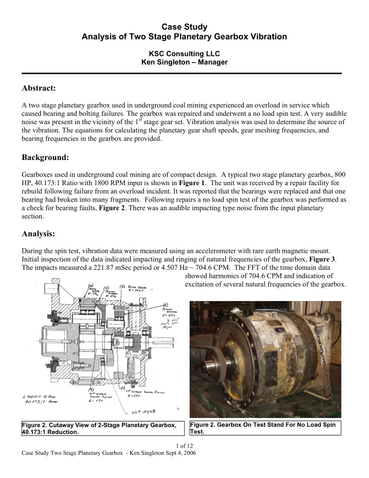
Case Study Analysis of Two Stage Planetary Gearbox Vibration KSC Consulting LLC Ken Singleton Manager Abstract: A two stage planetary gearbox used in underground coal mining experienced an overload in service which caused bearing and


  1. Case Study Analysis of Two Stage Planetary Gearbox Vibration KSC Consulting LLC Ken Singleton – Manager Abstract: A two stage planetary gearbox used in underground coal mining experienced an overload in service which caused bearing and bolting failures. The gearbox was repaired and underwent a no load spin test. A very audible noise was present in the vicinity of the 1 st stage gear set. Vibration analysis was used to determine the source of the vibration. The equations for calculating the planetary gear shaft speeds, gear meshing frequencies, and bearing frequencies in the gearbox are provided. Background: Gearboxes used in underground coal mining are of compact design. A typical two stage planetary gearbox, 800 HP, 40.173:1 Ratio with 1800 RPM input is shown in Figure 1 . The unit was received by a repair facility for rebuild following failure from an overload incident. It was reported that the bearings were replaced and that one bearing had broken into many fragments. Following repairs a no load spin test of the gearbox was performed as a check for bearing faults, Figure 2 . There was an audible impacting type noise from the input planetary section. Analysis: During the spin test, vibration data were measured using an accelerometer with rare earth magnetic mount. Initial inspection of the data indicated impacting and ringing of natural frequencies of the gearbox, Figure 3 . The impacts measured a 221.87 mSec period or 4.507 Hz ~ 704.6 CPM. The FFT of the time domain data showed harmonics of 704.6 CPM and indication of excitation of several natural frequencies of the gearbox. Figure 2. Cutaway View of 2-Stage Planetary Gearbox, Figure 2. Gearbox On Test Stand For No Load Spin Test. 40.173:1 Reduction. 1 of 12 Case Study Two Stage Planetary Gearbox - Ken Singleton Sept 4, 2006

  2. Before a determination of the source of the vibration could be made, an understanding of the gearbox design was required and calculation of the excitation frequencies. Based on the information provided by the drawing shown in Figure 1 , several calculations were made to obtain the shaft speeds, bearing fault frequencies and gear meshing frequencies. LW - Joy L700EP 40.173 SN-85836 -P2H Pt 2 Hor Input Shaft 0.12 Route Spectrum RMS Acceleration in G-s Resonance at about 16-Mar-06 08:48:16 66,000 CPM 0.09 OVERALL= .0802 V-AN RMS = .3892 LOAD = 100.0 0.06 RPM = 506. (8.44 Hz) 0.03 0 0 20000 40000 60000 80000 100000 Frequency in CPM 221.87 mSec ~ 4.507 Hz ~ 704.6 CPM 3 Route Waveform 2 16-Mar-06 08:48:16 Acceleration in G-s RMS = .3743 1 PK(+/-) = 2.17/2.15 CRESTF= 5.80 0 -1 -2 -3 0 1 2 3 4 5 6 7 8 9 Revolution Number Figure 3. Vibration Signal Measured at Gearbox Input Section Showed Impacts at 221.87 mSec Interval ~ 4.507 Hz ~ 704.6 CPM. The FFT (Top Plot) Indicated Excitation of Several Resonant Frequencies Including A Very Response One at About 66,000 CPM ~ 1,100 Hz. Epicyclic gear boxes derive their name from the epicyclodial curves that the planet gears produce during rotation. There are three general types of epicyclic arrangements, 1) planetary which consists of a stationary ring gear combined with a rotating sun gear and moving planet carrier, 2) star configuration which consists of a stationary planet carrier coupled with a rotating sun gear, and 3) solar gear that has a fixed sun gear combined with a moving ring gear and planet carrier. The planetary arrangement is most common and is shown by the schematic in Figure 4 . The subject gearbox had the planetary arrangement for the 1 st and 2 nd stages. Input was from the sun with three planets supported by a carrier revolving about the sun pinion and the ring gear fixed. 2 of 12 Case Study Two Stage Planetary Gearbox - Ken Singleton Sept 4, 2006

  3. 1 st Stage 2 nd Stage S S Sun Gear RPM (Input Speed) 1782 -234.838 R T Ring Gear Teeth 112 73 P T Planet Gear Teeth 47 27 S T Sun Gear Teeth 17 17 T value Train Value 0.151786 0.2328767 C S Carrier RPM -234.838 -44.358 P S Planet RPM 559.612 119.931 P Sabsolute Planet RPM Absolute -324.775 -75.573 R S Ring Gear RPM 0 0 P GMF Planet Gear Meshing Freq 26,301.76 3,238.14 CPM Figure 4. Gear Arrangement Of 1 st Stage F GMF-Sun Sun Gear Meshing Freq CPM 30,294.00 3,992.23 Ratio Stage Ratio 7.5882 5.2941 Planetary Input Section. Table 1: Summary of The Gearbox Shaft Speeds and Gear Meshing frequencies. Step 1: Carrier Speed The 1 st stage carrier speed can be calculated as follows: Train value: × × S P 17 47 = = = T T T 0.151786 Value × × P R 47 112 T T The 1 st stage Carrier Speed then calculates to: − × R T S − × − 0.151786 1782 270.48265 = S value S = = = − C 234.8376 RPM S − − − 1 T 1 ( 0.151786) 1.151786 value The negative sign “-“ indicates the carrier is rotating in the opposite direction to the sun gear. The 2 nd stage carrier speed which is also the output of the gearbox calculated to: × × S P 17 27 = = = T T T 0.2328767 Value × × P R 27 73 T T − × R T S − × − 0.2328767 234.8376 54.6882 = S value S = = = − C 44.3582 RPM S − − − 1 T 1 ( 0.2328767) 1.2328767 value The gearbox ratio calculated to: Input 1782 = = = R atio R PM 40.173 O utput 44.3586 R P M The calculated ratio agreed with the ratio provided by the gearbox manufacture of 40.173. 3 of 12 Case Study Two Stage Planetary Gearbox - Ken Singleton Sept 4, 2006

  4. The carrier speeds can also be calculated as follows: The 1 st stage carrier speed: + + R S 112 17 = = = R t t 7.5882 O S 17 t S 1782 = = = C S 234.838 RPM S R 7.588 O The 2 nd stage carrier speed: + + R S 73 17 = = = R t t 5.2941 O S 17 t S 234.838 = = = C S 44.358 RPM S R 5.2941 O 4 of 12 Case Study Two Stage Planetary Gearbox - Ken Singleton Sept 4, 2006

  5. Step 2: Planet Speed The 1 st stage planet rotational frequency or planet spin speed was calculated as follows: R 112 = • = • = P C T 234.838 559.613 RPM S S P 47 T The 1 st stage absolute planet rotational frequency can be determined by summing the carrier and planet rotational frequencies algebraically. Note that this frequency seldom appears in vibration data. = + = − + = P C P 234.838 559.612 324.775 RPM s s S Absolute The 2 nd stage planet spin speed calculated as follows: R 73 = • = • = P C T 44.3594 119.935 RPM S S P 27 T The 2 nd stage absolute planet rotational frequency is then determined: = + = − + = P C P 44.358 119.935 75.577 RPM s s s Absolute The planet speed can also be calculated as follows: 1 st stage planet RPM: R 112 = • − = • − = − P t ( R C ) ( 234.838) 559.614 RPM R S S P 47 t 2 nd stage planet RPM: R 73 = • − = • − = − P t ( R C ) ( 44.3594) 119.935 RPM R S S P 27 t 5 of 12 Case Study Two Stage Planetary Gearbox - Ken Singleton Sept 4, 2006

  6. Step 3: Gear Meshing Frequencies The planet gear meshing frequencies were then determined for stage 1 as follows: = × = × = P P P 559.612 47 26,301.76 CPM GMF S T The higher frequency sun gear meshing frequency was calculated: = × = × = S S S 1782 17 30,294 CPM GMF s T The 2 nd stage planet gear meshing frequencies were then determined as follows: = × = × = P P P 119.931 27 3,238.14 CPM GMF S T The 2 nd stage sun gear meshing frequency was then calculated: = × = × = S S S 234.8376 17 3,992.24 CPM GMF s T 6 of 12 Case Study Two Stage Planetary Gearbox - Ken Singleton Sept 4, 2006

Download Presentation
Download Policy: The content available on the website is offered to you 'AS IS' for your personal information and use only. It cannot be commercialized, licensed, or distributed on other websites without prior consent from the author. To download a presentation, simply click this link. If you encounter any difficulties during the download process, it's possible that the publisher has removed the file from their server.

Recommend


More recommend