
SLIDE 1
1
Review of Circuit Analysis
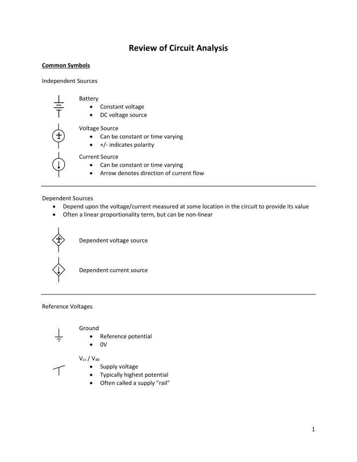
Common Symbols Independent Sources Battery
- Constant voltage
- DC voltage source
+
- Voltage Source
- Can be constant or time varying
- +/- indicates polarity
Current Source
- Can be constant or time varying
- Arrow denotes direction of current flow
Dependent Sources
- Depend upon the voltage/current measured at some location in the circuit to provide its value
- Often a linear proportionality term, but can be non-linear
+
- Dependent voltage source
Dependent current source Reference Voltages Ground
- Reference potential
- 0V
Vcc / Vdd
- Supply voltage
- Typically highest potential
- Often called a supply “rail”