
SLIDE 1
BP Bulwer Island Refinery 1965 - 2015 Good evening everyone and - - PowerPoint PPT Presentation
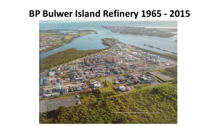
BP Bulwer Island Refinery 1965 - 2015 Good evening everyone and thanks for attending. It is my pleasure to be reminiscing about BP Bulwer Island Refinery. I started working at the refinery in 1987 and worked in many roles over my 29 year career
I will start with a bit of refinery history. It was constructed by Amoco in the mid 1960’s and came on stream in October 1965. BP subsequently acquired the refinery in July 1984. The refinery processed crude oil imported by tanker, although a small proportion was supplied by pipeline from oilfields in Queensland until the 1980s. The whole area on which refinery stands was originally a tidal mangrove swamp that was reclaimed using sand dredged from adjacent areas in Boggy Creek and the Brisbane River. Over the years there were many additional units added to the site and all of the original units were expanded. Although the refinery started with 25,000 BSD of crude oil processing capacity it was increased over the years to 102,000 BSD producing over 2 billion litres of motor spirit, 2 billion litres of diesel and 1 billion litres of Jet fuel every year. As well as improving capacity, many of the changes made over the years were to address changes to environmental licences and product quality specifications and to improve safety and margins. The offsites area contained 10 Crude Oil Storage tanks, 19 Intermediate storage tanks and 39 Finished Product
Pinkenba and Eagle Farm, the Brisbane Airport and across the river to Caltex Lytton Refinery. Recycled water was piped to the site from the Luggage Point Sewerage treatment plant.
I will briefly discuss the design of the plant. The process flow diagram shown depicts the refinery close to the time of closure. As mentioned much of this plant was added or modified over the years of operation. The Bulwer site made hydrogen, oxygen, nitrogen, argon, LPG, Auotgas, chemical propylene, butane, gasoline, kerosene, heating oil, jet fuel, diesel, fuel oil, sulphur and electricity. Bitumen was also made for most of the life of the refinery. Crude oil was processed through one of the two Crude distillation units. No. 1 crude and vacuum unit was an original 1965 unit modified over the years to increase capacity from 10,000 to 41,000 BSD. No.2 crude unit was added in 1978 at 25,000 BSD and modified to over 50,000 BSD in 1996. The deep cut vacuum unit was added in 2000 as part of the Queensland Clean Fuels Project to feed the new hydrocracker and increase crude flexibility. The Catalytic Cracker was an original unit in 1965 at 9,500 BSD and was continuously modified over the years to achieve 23,000 BSD and process much heavier feed. The Catalytic Cracker was always my favourite unit and was for much of the life of the refinery the money maker turning rubbish oil into gasoline and diesel. It was oxygen enriched, had a huge catalyst cooler and state of the art separation and feed nozzle design. The diesel hydrotreater shown, was an original 1965 unit, however it had been decommissioned 15 years before closure, as the new hydrocracker installed in 2000 could hydrotreat all of the diesel to less than 10 ppm sulphur. The low sulphur diesel significantly reduced smog and particulate emissions from diesel engines. The hydrocracker ran at over 2500 psig and consumed over 90 TPD of hydrogen provided by the partial oxidation Hydrogeneration Unit, owned by BOC but
An air separation unit, owned and operated by BOC, was also added to the Bulwer site in 2000 to provide
sulphur plant. The No.1 Sulphur recovery unit shown here was built in 1982 and replaced the original 1969 unit. The No.2 Sulphur Unit was added in 2000 to handle extra sulphur generated by the hydrocracker as well as a sulphur priller was built to solidify sulphur. The Hydroflouric Acid Alkylation unit was added in 1969 to convert C4s to gasoline and was decommissioned a couple of years before closure. It represented one of the greatest risks on the refinery with the potential for far reaching implications beyond the refinery gate. The reformer that was originally installed in 1965 was replaced in 1978 with the unit shown here and underwent significant modifications over the years to enable lead to be removed from gasoline, increase rate and meet higher octane specs. The capacity was increased from 9000 BSD to over 15,000 BSD over its life. It was a semi-regenerative design. The South Vapour Recovery Unit is associated with the Catalytic Cracker and was built in 1965, but also modified extensively over the years. The North Vapour Recovery unit was similar to the South unit however processed LPG from the crude units, hydrocracker and reformer. Along with the Naphtha Splitter, this unit was built in the 1980’s and reused some equipment from BP Westernport Refinery that had been shut down.
The Propylene Saturation Unit was built in the early 2000’s to handle excess propylenes and meet Autogas and LPG specifications. The Benzene Saturation Unit was built in 2005 to meet new gasoline specifications. The Cogeneration Unit was built in 2000 with Queensland Clean Fuels Project to provide steam and power to the site from refinery and natural gases. It was owned by BIEP but operated by the refinery. Although about $2 billion per year of crude oil was processed through the refinery, gross margins were in the hundreds of millions per year and net margins on a good year somewhere between zero and $150 million. The refinery configuration allowed it to process a wide variety of crude feedstocks including residues, condensates and even tallow and palm oil.
The original refinery was built before computers and digitization. It was built with analogue controls with some field stations for the boilers. The control room even had some samples pass through translucent tubes in the control room for visual inspection. The control room was digitized in the 1980s and in 1996 a new distributed control system was implemented within a new blast resistant Central Control Building. Digitization also resulted in a continuous evolution of computer tools for modelling, optimization, design and training. The refinery was always at the forefront of new technologies which made it an exciting and interesting place to work. Just prior to the closure announcement, high fidelity operator training simulators built from first principles models were being installed at the refinery. They had the capability to accurately represent the refinery under almost any scenario and could represent the interactions of operators both in the control room and in the field. I was so amazed at its capability, when I finished at BP, I decided to conduct research into how these dynamic models, extracted from simulators can be used within the digital twin and Industry 4.0 concept to improve process hazard analysis.
Being an oil refinery, everything didn’t always go as intended and often it was obvious to the outside world. The picture shows a large flaring event as a result of interruption to the ‘uninterruptable’ instrument power. Murphy’s Law holds up when you hang around long enough - anything that can go wrong will go wrong. Instrument power was supplied via two independent parallel systems designed to withstand any common mode or individual equipment item failures and hence its name as ‘uninterruptable’. We had a component failure in one of the parallel systems. When the instrument mechanic commenced rectification work, he incorrectly isolated the operating power supply taking out all instrument power. This is one of the worst things to do to a refinery as not only do all controls and valves go to fail safe causing loss of utilities and operating units, but you also lose the DCS screens and the ability to monitor the operation. The No.1 vacuum tower filled shortly afterwards spraying hot residual oil over a large area of the refinery. Human error events such as this are not unusual.
I have had many experiences over the years, but I thought I would share a few more war stories that taught me a lot. In my early days as an operating superintendent I accidentally caused a shut down the refinery with no way to restart. I was fortunate to have an understanding boss at the time. We were taking a crude unit furnace out of service for a decoke. A modification had been made prior to my time, where a small change was made to the boiler feed water piping such that the preheat coil went from series to parallel flow with another furnace coil. We followed the procedure when taking the crude furnace offline, however opening the bypass now starved a running furnace of its flow. The temperatures within the furnace coils went off scale causing the measurements to go bad value, deactivating the alarms and the loss of flow was not detected. About 1 week later the tube ruptured on an external elbow causing almost a complete loss of BFW to the steam generators, site wide loss
In those days we didn’t have natural gas to the refinery, which meant that without the operating units making gas or the ability to atomise fuel oil with steam we had no way to fuel the boilers. To get the refinery started required significant ingenuity and persistence by all involved. We built personnel shields out of sheet metal to provide access to isolate the burst coil under a raining cloud of boiling water and sprayed firewater on the outside of pipes to vapourize the LPG to sufficiently operate the boiler until enough steam could be generated. Once we had steam to vapourize the LPG for fuel we got the boilers running and eventually restarted the refinery. This early experience taught me to never assume anything. Always check things out for yourself if you are responsible ……because you never know.
In 1996 I gained a deeper appreciation for the energy contained within a refinery. At one stage during this incident I stood at the base of this stack and we had a plume of yellow smoke from the bypass stack and plume of black smoke from the furnace stack. The initial wind conditions were stagnant and it looked like we touched the stratosphere which really shocked me. We had been in the process of moving control to the new central control building and a wire was accidentally shorted that slammed closed the regenerated catalyst slide valve on the Catalytic Cracker. This caused the riser to fill with un-vapourized oil and a feed forward reversal of oil to the regenerator. Although we had installed a trip system to avoid reversals, following a similar event in 1987 where we destroyed a furnace, it could not act quickly enough to prevent the reversal. At the time, we had hundreds of external contractors on site preparing for a site wide turnaround and multiple unit revamps. They evacuated the site and it required a lot of discussion to convince them that it was safe to return. There have been a couple of Catalytic Cracker reversals in the last few years at Exxon Mobil and Husky refineries that resulted in explosions and extensive damage.
In 2010 Bulwer Island recorded the largest spill within BP that year at 180, 000 litres of oil. Although most of this was contained in a bunded area, there was a high risk of fire and required extensive remediation. We had been having problems with tank mixer seal leaks and with all the best intentions, someone decided to improve the locking grub screw arrangement by adding a second grub screw on top, to lock the original screw in place. Unfortunately this change was not considered under management of change processes, which resulted in the fitter who reinstalled the mixer being unaware of the change and locking down only the top grub screw. Although the mixer was recommissioned without issue, the seal arrangement loosened over a short period of operation causing the seal to leak extensively and went unnoticed for 24 hours. It was discovered by a contractor in the offistes area who noticed the bund was full of black oil and alerted operations. This incident demonstrates that no matter how small a change, it needs to undergo consideration through a management of change process.
One final incident I wanted to share with you is from very late in my career, when I thought I had seen most things. It was a failure of a SIL3 safety instrumented system on the hydrogen unit which was the highest integrity level safety system on site, with an expected failure on demand rate of 1 in 10000….were we just unlucky? The hydrogen unit partially oxidised gas streams with pure oxygen and was one of the highest explosive risks in the refinery. The trip system had not been trip tested within its designated period although it had experienced operating trips where it appeared to work
Authority, I was asked to approve an extension to the due date for the trip test. Before the analysis was complete, the unit experienced an unplanned shutdown. When we tested the SIL3 trip system as part of the shutdown, it did not work. When we investigated the failure, we discovered that the exhaust vents on the actuators were blocked preventing closure of the isolation valves. Although we had implemented screens to prevent mud dauber wasps building nests in the vents, the mesh exhaust silencers that were made of brass and aluminium had corroded and blocked in the saline environment near the mouth of the river. When we closely interrogated historical data from previous operating trips we could see that closure times had been gradually increasing over the years, and were exceeding process safety times but we had not noticed this. We also discovered similar issues across other isolation valves on the refinery that used these same exhaust vents and blockages in other types of screens. I shudder to think of the repercussions if the unit had been allowed to continue to operate without enforcing the trip test. My learning was that even when you think you have got huge risk protected, you need to be really sure that your barriers will work when needed and understand their failure mechanisms…and on a more mechanical level…the weakest link in automated isolation valves are the actuator
will close in time. If you don’t have screens are there mud dauber wasps nesting in the vent? These were just a small selection of some the trials and tribulations operating a refinery. We tried to learn from our failures and continuously improve.
Working at the refinery taught me to be attentive to weak signals, ask lots of questions, get to the root causes of problems, remove the defects, learn from the past, respect your elders and listen to old ‘war stories’, maintain integrity in everything you do, respect the perspectives of all that you work with, get your hands dirty, get involved, blend in and learn new things every day. The refinery was a high complexity modern refinery with high reliability, a great safety record and had highly competent and experienced personnel. Most people who started work at the refinery stayed there their whole lives and this made a big difference for all that came after. Prior to the refinery closure announcement there were 355 BP employees and over 200 hundred of contractors working on site. It was a great place to work and BP was a great company to work for. I miss the refinery and the great people I worked with. I will now hand over to Tim who can provide context as to the decision to cease operation in 2015.