
SLIDE 1
1
Objects and Transformations Before we begin
- Paper summaries for today?
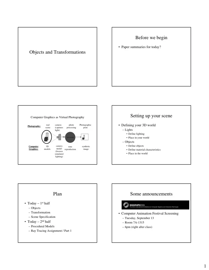
Computer Graphics as Virtual Photography
camera (captures light) synthetic image camera model (focuses simulated lighting)
processing
photo processing tone reproduction real scene 3D models Photography: Computer Graphics: Photographic print
Setting up your scene
- Defining your 3D world
– Lights
- Define lighting
- Place in your world
– Objects
- Define objects
- Define material characteristics
- Place in the world
Plan
- Today – 1st half
– Objects – Transformation – Scene Specification
- Today – 2nd half
– Procedural Models – Ray Tracing Assignment / Part 1
Some announcements
- Computer Animation Festival Screening
– Tuesday, September 13 – Room 7A-1315 – 6pm (right after class)