B 1.7384 RM Mini Slide with optional position monitoring double - - PDF document

b 1 7384
SMART_READER_LITE
LIVE PREVIEW

B 1.7384 RM Mini Slide with optional position monitoring double - - PDF document

Issue 2-07 E B 1.7384 RM Mini Slide with optional position monitoring double acting, max. operating pressure 500 bar Description Advantages The RM mini slide is a compact block cylinder 4 sizes each with 3 stroke lengths with 4


slide-1
SLIDE 1

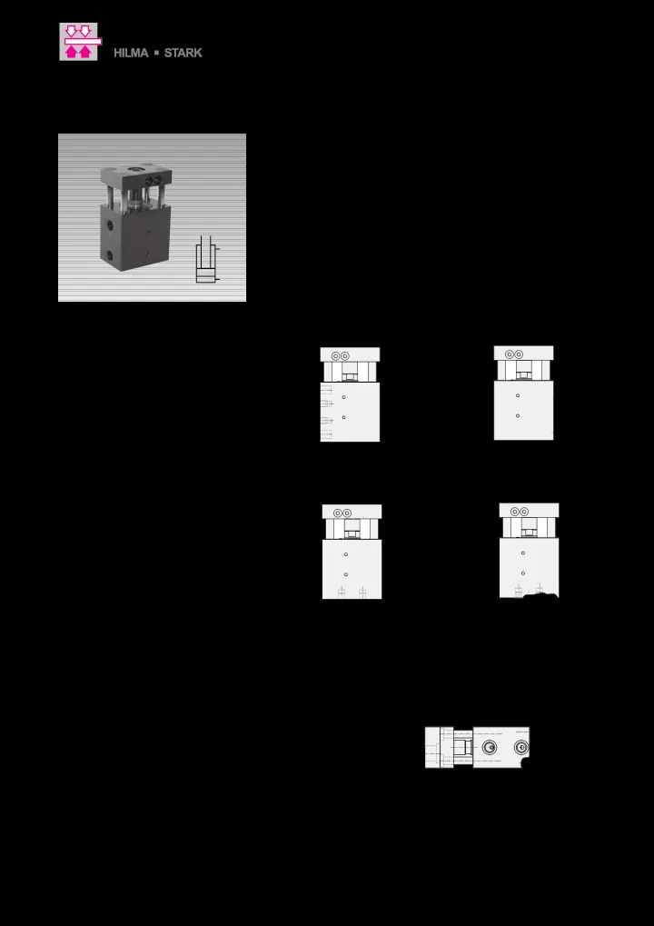
Fixing possibilities Connecting possibilities Application example for deburring tools Cylinders must be backed up for operating pressures exceeding 100 bar or secured by dowel pins. Areas of application ➢ Tool manufacture ➢ Mould making ➢ Metal forming ➢ Pressing ➢ Punching ➢ Deburring ➢ Perforating ➢ Power workholding ➢ Assembly technology Important notes The RM mini slide must never be operated with the delivered front block only, i.e. without working load (see application example). Reason: In order to spare overall length, the guide rods with collar are plugged in from the front into the counterbores of the front block. Locking in the other direction has to be effec- ted by the screwed on working load (tool fixing plate). All 4 counterbores have to be covered at least partially (see page 4). The safety distance of 25 mm between the front block and the cylinder has to avoid squeezing of the fingers. A complete protec- tion is however only possible by mounting further safety devices, which is the responsi- bility of the machine tool manufacturer. If the RM mini slide is secured so that injuries

  • f the operator are excluded even in the

setting mode, the distance bushing between the front block and the piston rod can be

  • removed. The total length is reduced by 15 up

to 18 mm (dimension c1). The RM mini slide has to be efficiently protec- ted against swarf, aggressive coolants and welding spatter. Operating conditions, tolerances and other data see data sheet A 0.100. See also recomendations on page 5. Advantages

  • 4 sizes each with 3 stroke lengths
  • Compact block design
  • 2 fixing possibilities
  • 2 connecting possibilities
  • Guide rods made of nitriding steel
  • Safety distance against squeezing
  • f fingers
  • Optional position monitoring

with limit switches or inductive sensors

  • Standard FKM-seals
  • Temperature range –20...+150 °C
  • Maintenance free

Description The RM mini slide is a compact block cylinder with 4 integrated guide rods which are also in the position to compensate side loads and moments. Threads can be provided in the front block for fixing of the working loads or tools (see page 4). To avoid a possible point of squeezing between the front block and the cylinder the safety distance of 25 mm as per DIN EN 349 is maintained. The RM mini slides can certainly be delivery equipped with position monitoring by limit switches or inductive sensors (see page 6).

Subject to change without prior notice

Römheld GmbH · Postfach 1253 · 35317 Laubach, Germany · Tel.: +49 (0) 64 05 / 89-0 · Fax: +49 (0) 64 05 / 89-21 1 Actual issue see www.roemheld.com

B 1.7384

Issue 2-07 E

RM Mini Slide with optional position monitoring double acting, max. operating pressure 500 bar

slide-2
SLIDE 2

a1 x1 11,5±0.02 x c1 c s l2 l1 z 25 d M 4x4 l D a 0.02 A / / 0.02 A 0.02 A / / A f1 f±0.02* g h1 h±0.02* e a b/2 f1 f±0.02* e a/2 t h±0.02* b h1 g v1 w v2 u Ra≤0,8

Versions with connecting thread Version for manifold mounting with O-ring sealing

b1 k

  • b/2

b i i r k1±0.02* m b/2 p n 13 6 M 5 Ø 10H7 Exact dimensions

  • f the front block

see page 4 * Tolerance ±0,02 is only valid for dowel holes oH7 and eH7 Distance bushing see important notes Retracting Extending Subject to change without prior notice B 1.7384 / 2-07 E

Technical data and dimensions

2 Actual issue see www.roemheld.com Römheld GmbH

slide-3
SLIDE 3

Piston Ø D [mm] 25 32 40 50 Rod Ø d [mm] 16 20 25 32 Force to push at100 bar [kN] 4.9 8 12.6 19.5 500 bar [kN] 24.5 40.2 62.8 98.5 Force to pull at 100 bar [kN] 2.9 4.9 7.7 11.6 500 bar [kN] 14.5 24.5 38.3 57.9 Oil volume per Stroke to extend [cm3] 4.91 8.05 12.56 19.63 10 mm stroke Stroke to retract [cm3] 2.9 4.9 7.7 11.6 a [mm] 65 75 85 100 a1 [mm] 64 74 84 99 b [mm] 45 55 63 75 b1 [mm] 44 54 62 74 c [mm] 7 10 10 10 c1 [mm] 18 15 15 15 e [mm] 8H7x8 deep 8H7x8 deep 10H7x10 deep 12H7x12 deep f [mm] 26 26 33 40 f1 [mm] 19.5 24.5 26 30 g [mm] M8x9 M8x9 M10x10 M12x12 h [mm] 32 40 48 57 h1 [mm] 6.5 7.5 7.5 9 i [mm] 24 27 28 34 k [mm] 10 10 11 14 k1 [mm] 24 + stroke 30 + stroke 32 + stroke 37 + stroke l1 [mm] 25 25 25 25 l2 [mm] 15 18 25 28 m [mm] 11 11 11 13 n [mm] 18 22 24 27

  • [mm]

8H7x8 deep 10H7x10 deep 12H7x10 deep 16H7x13 deep p G 1/4 G 1/4 G 1/4 G 1/4 r [mm] M 8x8 M 8x8 M 10x10 M 12x12 s [mm] 8 10 12 16 t [mm] 25 27.5 31.5 38 w +0.2 [mm] 9.8 9.8 9.8 10.8 u ±0.05 [mm] 1.1 1.1 1.1 1.1 v1 extend [mm] 4 5 6 6 v2 retract [mm] 4 4.5 4.5 6 z ±0.2 [mm] 25 19 22 32 Dimensions O-ring 7x1.5 7x1.5 7x1.5 8x1.5 Part-no. O-ring (FKM) 3001-077 3001-077 3001-077 3000-275 Part-no. double acting with connecting thread Stroke ±1 [mm] 20 25 25 25 Total length l ±1 [mm] 104 118 129 143 Weight [kg] 1.6 2.8 4.1 6.4 Part-no. RM3-020-10 RM4-025-10 RM5-025-10 RM6-025-10 Stroke ±1 [mm] 50 50 50 50 Total length l ±1 [mm] 134 143 154 168 Weight [kg] 2.2 3.7 5.1 7.8 Part-no. RM3-050-10 RM4-050-10 RM5-050-10 RM6-050-10 Stroke ±1 [mm] 100 100 100 100 Total length l ±1 [mm] 184 193 204 218 Weight [kg] 3.8 5.5 7.1 10.8 Part-no. RM3-100-10 RM4-100-10 RM5-100-10 RM6-100-10 Temperature range –20...+150 °C For versions with position monitoring consider environmental temperature of the switches indicated on page 6. Code for part-nos.: RMX-XXX-10 - version without position monitoring RMX-XXX-11 - version with 1 inductive sensor at the right side RMX-XXX-12 - version with 2 inductive sensors at the right side RMX-XXX-13 - version with 1 limit switch at the right side RMX-XXX-14 - version with 2 limit switches at the right side RMX-XXX-15 - version with 1 inductive sensor at the left side RMX-XXX-16 - version with 2 inductive sensors at the left side RMX-XXX-17 - version with 1 limit switch at the left side RMX-XXX-18 - version with 2 limit switches at the left side Versions for manifold mounting with O-ring sealing at the bottom (O-rings are included in the delivery). RMX-XXX-XXB

Subject to change without prior notice B 1.7384 / 2-07 E

Part numbers

Römheld GmbH Actual issue see www.roemheld.com 3

slide-4
SLIDE 4

a1 a2±0.02 Ø 10H7 b1 b2±0.02 6 13 16 x x1

+0.1 +0.2

t2 l 2 sH7 m2 s1 11,5±0.02 t1 m1

25 45,5

22,5

45,5

Dimensioning of the front block To fix the working load (tool fixing plate) threads and possibly dowel holes have to provided in the front block. The exact dimensioning

  • f the front plate facilitates their arrangement so that a collision with

existing bore holes can be avoided. The tool fixing plate has to cover at least partially the 4 counterbores. RM3 RM4 RM5 RM6 a1 64 74 84 99 a2 48 55 61 74 b1 44 54 62 74 b2 28 35 38 45 l2 15 18 25 28 t1 5 5 7 7 t2 11 13 18 22 m1 10,5 13 17 21 m2 18 20 26 33 s 8 10 12 16 s1 14 16 18 22 x 9 11 12 11 x1 19.25 19.25 21.25 24.25 Weight [kg] 0.25 0.44 0.80 1.20 Part-no. 3538-568 3538-569 3538-570 3538-571 Position of the position monitoring Single inductive monitoring RMX-XXX-11 = monitoring at the right side RMX-XXX-15 = monitoring at the left side Single limit switch monitoring RMX-XXX-13 = monitoring at the right side RMX-XXX-17 = monitoring at the left side Double inductive monitoring RMX-XXX-12 = monitoring at the right side RMX-XXX-16 = monitoring at the left side Double limit switch monitoring RMX-XXX-14 = monitoring at the right side RMX-XXX-18 = monitoring at the left side

15 11 16 12 17 13 18 14

The switching point is selectable by displacing the control cam on the switch rod.

Subject to change without prior notice B 1.7384 / 2-07 E

Dimensioning of the front block Position of the position monitoring

Römheld GmbH Actual issue see www.roemheld.com 4

slide-5
SLIDE 5

RM6 RM5 RM3 RM4

10 20 30 70 80 40 50 60 90 100 50 100 150 200 250 300 350 400

RM6 RM5 RM3 RM4

10 20 30 70 80 40 50 60 90 100 50 100 150 200 250 300 350 400

RM6 RM5 RM3 RM4

500 1000 2000 3000 4000 10 20 30 70 80 40 50 60 90 100 5000

F

Load of the front block If the front block is loaded with side loads and moments, guide rods will be deformed. This deformation is as bigger as longer the stroke. The following assumptions are valid for the maximum moments and side loads recommended in the diagrams: The maximum side load as per diagram utilizes the whole capacity of the guide rods regardless of their deflection. For the recom- mended moments a limit value of 0.1 mm is

  • assumed. Certainly the system will withstand

considerably higher values, but the defor- mations are no longer acceptable in

  • applications. Here the RM mini slide reaches

its limits. Recommendations:

  • 1. Introduce the forces in the centre of the

guide plate to use the force potential of the RM mini slide.

  • 2. Select the cylinder stroke as short as

possible.

  • 3. Keep the working load (tool weight) as low

as possible.

  • 4. The RM mini slide has no stroke end
  • cushioning. Therefore do not use the whole

stroke, but push the tool against an exter- nal stop. This is above all indicated for high loads and/or high piston speed.

Stroke [mm] My / Mz [Nm] Stroke [mm] Mx [Nm] Stroke [mm] F [N] Maximum side load F as a function of the stroke Recommended maximum moments as a function of the stroke

F Mz Mx

Mx My

My

1.Moment Mx must distort the front block by maximally 0.1 mm.

  • 2. The moments My or Mz may tilt the front

block by maximally 0.1 mm.

  • 3. The maximum side load F must not exceed

the admissible load of the rod guide.

0.1 max. 0.1 max. Subject to change without prior notice B 1.7384 / 2-07 E

Moments and side loads Recommendations

5 Actual issue see www.roemheld.com Römheld GmbH

slide-6
SLIDE 6

M 8x1 SW 13 LED 45,5 54,5 1 4 3 21 13 22 14 Ø 6 45 9,5 12,5 13,5 22 27 50 M 16x1,5 25

Inductive sensor

General characteristics Type of installation flush mounting Rated operating distance Sn [mm] 1.5 Secured operating distance Sa [mm] 0...1.2 Repeatability [%] ≤ 5 Hysteresis [%] ≤ 15 Environmental temperature [°C]

  • 25...+70

Degree of contamination 3 Stand-by delay [ms] ≤ 10 Mechanical characteristics Shape in mm [mm] M 8 Material of the body stainless steel Material of sensing face PBTP Code class [IP] IP 67 Connection plug S49 Electrical characteristics Voltage DC Wiring 3 wires Switching function interlock Output signal pnp Rated operating voltage [V] 24 DC Rated operating current [mA] 200 Operating voltage Ub [V] 10...30 DC Residual ripple % of Ub ≤ 15 Mains frequency [Hz] Switching frequency [Hz] 3000 No-load current [mA] ≤ 8/≤ 1 Voltage drop [V] ≤ 1.5/- Short circuit protection yes Protection against reverse battery yes Part-no. 3829-164

Limit switch

Material of the body aluminium diecasting Code class as per DIN 40050 IP67 Class as per VDE 0660 part 200 30x106 mechanical switching examples Environmental temperature [°C]

  • 5 up to +80

Switching principle snap switch Switching elements 1 make contact + 1 break contact Connection soldered connection Cross section

  • f the connection max.

[mm2] 1 Make time [ms] < 5 Bounce time [ms] < 3

  • Max. switching frequency

[min-1] 200 Nominal switch off capacity 24V/2A Switching voltage min. [V] 12

  • Min. switching current at 12 V

[mA] 10 Short circuit protection (control fuse) 6A slow -10A fast Part-no. 3829-222

Switching point Off-position BN BK BU

Accessories for inductive sensor Connecting cable with right angle plug Voltage 10 – 30 V DC Protection as per DIN 40050 IP 67 Environmental temperature –25°C up to +90°C Plug connection M8 plug LED Voltage (green) Function display (yellow) Cable, length of cable PIR, 5 m Output, interlock pnp npn Part-no. (1 off) 3829-099 3829-124

Counterbore for socket head cap screw M4 DIN 912 Subject to change without prior notice B 1.7384 / 2-07 E

Technical data Inductive sensor • Limit switch

6 Actual issue see www.roemheld.com Römheld GmbH